Modeling a Classic Airliner Nose in CAD with Primary Surfacing Techniques
Summary:
This video demonstrates the "proper" method for modeling a classic airliner nose in CAD software, focusing on primary surfacing techniques.
- The process begins by setting up planar degree-three guide curves from a 3-view drawing of a Convair 240.
- The nose is modeled in two halves (top and bottom) to maintain control and utilize symmetry.
- A key technique involves converting three-sided holes into four-sided holes using a "trimmed corner" approach, avoiding surface quality issues like puckers or wrinkles.
- Surfaces are created from edge curves and iteratively matched for tangency, with the surface degree being increased as needed to achieve precise continuity.
- The speaker emphasizes analyzing tangency breaks using tools like global matching analysis to ensure high surface quality (below 0.2 degrees).
- Best practices include ensuring guide curves allow for desired continuity targets and matching new surfaces to primary guide surfaces rather than adjacent modeled surfaces for critical edges.
- The result is a smooth, high-quality, watertight airliner nose model free of singularities.

The final, complete airliner nose model integrated with the original Convair 240 blueprint. [ 00:21:36 ]
Introduction to Modeling a Classic Airliner Nose [0:00]
- The video introduces an example of modeling a classic airliner nose to tie together surfacing concepts from previous episodes.
- The Convair 240, a 1950s prop liner, is chosen as the reference.
- The focus is on accurately modeling the nose section, described as a common challenge for many modelers.
- Common pitfalls in nose modeling [0:44]
- Lofting into a point, leading to loss of control and surface quality issues like puckers or wrinkles.
- Lofting most of it and using a patch function to fill a circular hole, also resulting in quality or control loss.
- The presented method aims for a "proper," clean, and smooth nose that adheres to input geometry without these issues.
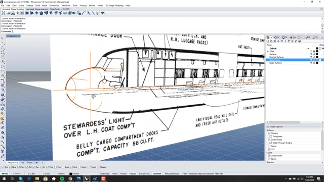
The Convair 240 3-view drawing with initial guide curves laid out in CAD software. [ 00:02:35 ]
Setting Up Guide Curves and Understanding Continuity [1:44]
- Generating Guide Curves [1:44]
- All guide curves are created as degree three and are planar.
- The nose is conceptually divided into top and bottom halves, which will be modeled separately and then mirrored.
- This approach is common for shapes that are "kind of a body of revolution but definitely not."
- Continuity Considerations [3:12]
- Guide curves are set to tangency, meaning the resulting surfaces should not be expected to have greater continuity than tangency if they adhere to these curves.
- Trying to achieve curvature continuity while strictly adhering to tangency-only guide curves would result in not following the guides.
- This highlights a common issue where initial guide curves limit the achievable continuity of the final model.
- For this example, the target continuity is tangency, making it a simpler case, while curvature continuous modeling would be more complex.
Modeling the Top Half of the Nose [4:56]
- Initial Surface Creation [4:56]
- The speaker turns off the 3-view to focus on the curves.
- Guide extrusions are created from cross-section curves.
- An initial four-sided surface is created using
Surface from Edge Curvesby splitting an oversized edge.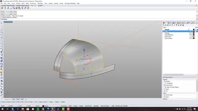
The first four-sided surface created for the top half of the airliner nose, based on guide curves. [ 00:06:49 ] - The surface is a single span, degree 3 in both directions.
- Matching for Tangency [7:07]
Match Surfis used to ensure tangency to the adjacent extruded guide surfaces.- The
Match Target Iso Curve Directionoption is selected. VSR Global Matching Analysisconfirms that the tangency (G1) is at absolute zero.
VSR Global Matching Analysis confirms perfect tangency (G1) for the initial surface. [ 00:07:39 ]
- Addressing the Three-Sided Hole with a Trimmed Corner [8:07]
- The current state presents a three-sided hole at the front of the nose.
- This is resolved by trimming back and using a "trimmed corner" technique, converting it into a four-sided hole to maintain control and avoid singularities (pinching/wrinkling).
- The main surface is split by an iso curve.
- A sphere is used to create an even setback, and its intersection curve is extracted.
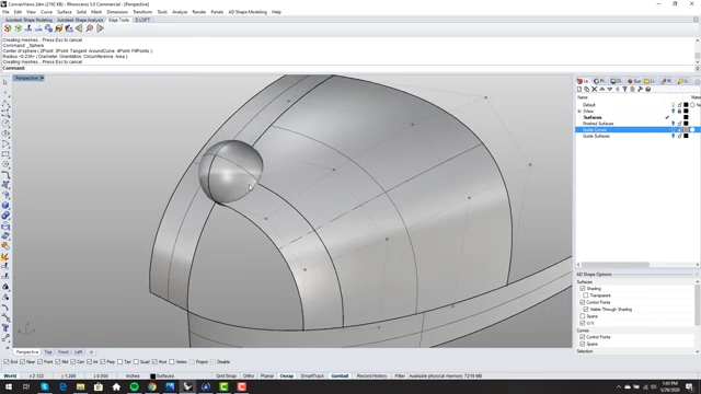
A sphere is used to create an even setback, transforming a three-sided hole into a four-sided one. [ 00:09:09 ] - A
Blend Curveis created between the extracted iso curve and the existing edge, with curvature continuity on one side and tangency across the centerline.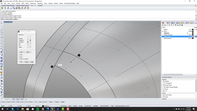
Creating a blend curve with curvature continuity on one side and tangency across the centerline. [ 00:09:30 ] - Edges are merged and re-split to define the new four-sided hole correctly.
- Iterative Surface Matching and Refinement [10:32]
- A new surface is created for the four-sided hole using
Surface from Edge Curves. - The control points (
f10) are checked, revealing the surface degree (degree 4 in one direction, degree 3 in the other).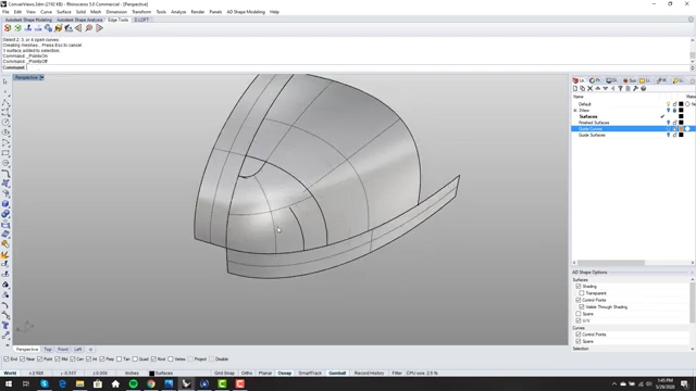
Control points (F10) displayed on the new four-sided surface, showing its degree (degree 4x3). [ 00:10:48 ] Match Surfis applied to the newly created surface's edges to achieve tangency with adjacent surfaces, matching iso curve direction.- Initial global matching analysis shows small tangency breaks (e.g., 0.07, 0.02 degrees).
- To improve continuity, the surface degree is increased (
Change Degree) (e.g., U from 3 to 4, V from 4 to 5). - Multiple matches are performed on all relevant edges (excluding the trimmed edge initially) to re-establish tangency.
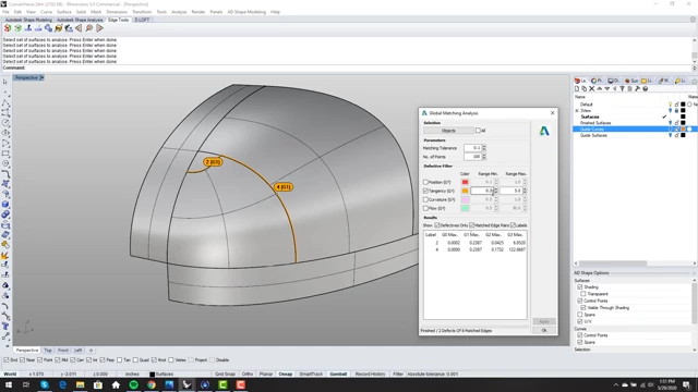
Global Matching Analysis showing tangency deviations above the 0.2-degree threshold before final degree increase and matching. [ 00:17:07 ] - The process is repeated: the trimmed edge is split off, deleted, and the main surface is matched again using
Preserve Iso Curve DirectionandMatch Closest Pointsfor the trimmed edge. - Further degree changes (U from 4 to 5, V from 5 to 6) and matching of all four edges simultaneously further reduce tangency breaks (e.g., to 0.03-0.04 degrees), achieving very high quality.
- A new surface is created for the four-sided hole using
Constructing the Bottom Half and Final Assembly [19:19]
- The bottom surface is constructed using the exact same methodology as the top half.
- A critical best practice for the common edge between the top and bottom halves:
- Instead of matching the bottom surface edge to the top surface edge, match both to the original guide curve that defines their common boundary.
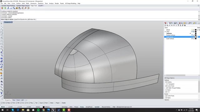
The completed top half of the airliner nose model after iterative matching and trimming. [ 00:18:42 ] - This prevents potential accumulation of small deviations (e.g., 0.1 degrees) from each surface, ensuring the central guide dictates the form.
- Instead of matching the bottom surface edge to the top surface edge, match both to the original guide curve that defines their common boundary.
Best Practices and Final Review [20:30]
- The finished nose is a smooth, watertight surface, adhering to the original Convair 240 design.
- The final model exhibits extremely low tangency deviations (largest break around 0.13 degrees, well below the 0.2-degree target).
The final, complete airliner nose model integrated with the original Convair 240 blueprint. [ 00:21:36 ] - The
trimmed cornertechnique effectively avoids singularities, pinching, or wrinkling common in other methods. - The importance of clean, planar, and well-defined input curves is reiterated, as they significantly simplify the surfacing process and improve final surface quality.

Final Global Matching Analysis for the complete nose model, demonstrating extremely low tangency deviations. [ 00:21:56 ]