Reviving a $40,000 Industrial Robot for $300 with a Custom Open-Source Controller and Public Operation
This video details the process of bringing an abandoned industrial robot back to life using a custom, open-source controller.
- The creator acquired a Yasawa Motoman UP6 robot for $300, a fraction of its original $40,000 value, to demonstrate how old industrial machinery can be made functional again.
- The core of the new controller is built around a Zynq 7020 chip, which combines a real-time Linux CPU and an FPGA for flexible custom interfaces and processing modules.
- Significant challenges included reverse-engineering proprietary encoder data protocols for the robot's motors and overcoming power supply and drive issues, such as a MOSFET failure and underrated inductors.
- The robot's J4 joint was upgraded for infinite rotation using slip rings, and a 6D mouse was integrated for intuitive, real-time control by mapping its movements to the robot's end position via inverse kinematics.
- Comprehensive safety measures, including an E-stop board and laser scanners, were implemented to create a secure environment for public interaction.
- The system was successfully showcased at the Open Sauce event, where attendees could control the robot to stack foam blocks.

A vast warehouse filled with discarded industrial robots [ 00:00:10 ] 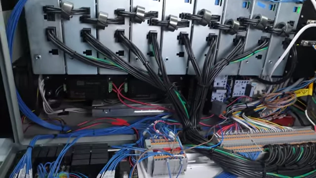
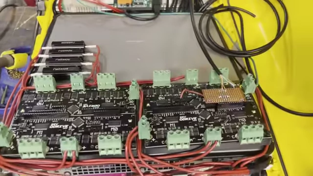
The custom-built, open-source robot controller featuring numerous servo drives [ 00:03:10 ] 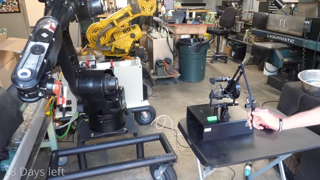
The robot arm precisely manipulating a colorful foam block using intuitive control [ 00:23:18 ] 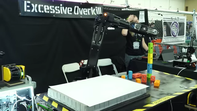
The completed industrial robot setup at the Open Sauce event with people interacting [ 00:36:27 ]
Intro [00:00]
Industrial robots and other machines often get discarded when they are no longer reliable enough for factories, making them available for a fraction of their original cost at auctions or surplus stores. This video showcases the process of bringing such an abandoned robot back to life.
Why Cheap Robots Aren't Usable [00:35]
While the mechanical parts of old industrial machines often remain robust, their electronic components frequently become obsolete or fail.
- Outdated Electronics: Many machines are decades old, making their electronics incompatible with modern computers or software, or simply prone to failure.
- Memory Loss: Some machines can lose their main memory if left unpowered for too long, as they rely on internal batteries to retain critical programming.
- These batteries are often not easily replaceable, leading to "planned obsolescence" as manufacturers don't provide easy fixes or documentation.
- Manufacturers typically offer little support for fixing these older, proprietary systems without significant cost.
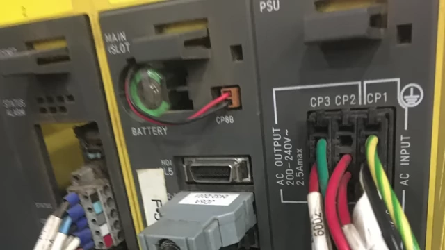
A close-up of a power supply unit with a battery slot labeled "BATTERY" [ 00:01:30 ]

I Bought One Anyway [01:45]
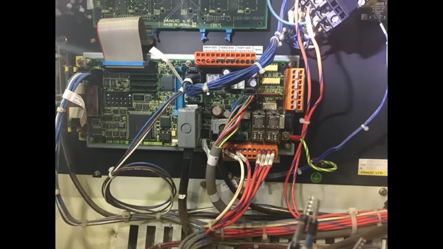
The creator acquired several old machines, including a Fanuc R2000 industrial robot.
- An example of an inexpensive Fanuc robot listed for $136, originally worth much more.
-

A screenshot showing a Fanuc R-2000ia/210f Robot listed for $136 [ 00:00:30 ]
-
- Another robot, a Motoman, with an original new price of $40,000, illustrating the potential savings.
-

A screenshot showing a Motoman robot listed with its original new price of $40,000 [ 00:00:32 ]
-
- One robot only needed a fuse replacement.
- Another robot, a Fanuc, had a fully functional mechanical arm, but its controller was mismatched (robot #8 with controller #13) and had incorrect settings (joint lengths, gear ratios), rendering it unusable for precise movements.
-
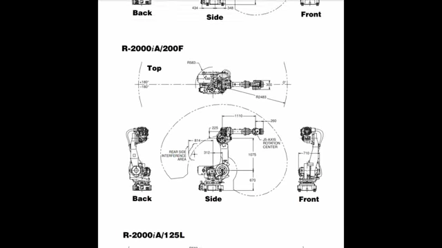
A diagram outlining the dimensions and joint limits of a robot arm [ 00:02:25 ]
-
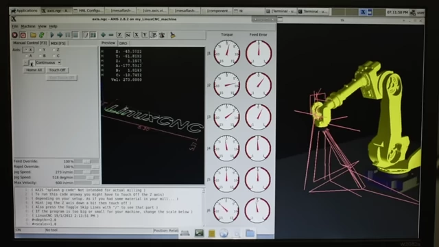
- An initial attempt in 2022 to build an open-source controller using LinuxCNC and O-drives was not very successful.
- Two years later, a dedicated effort resulted in a robust, open-source controller capable of running various industrial robots without proprietary hardware or software.
-
The custom-built, open-source robot controller with internal wiring and multiple servo drives [ 00:03:10 ]
-
Core of the New Controller [03:26]
The brain of the new controller is a Zynq 7020 chip, which integrates two CPU cores running real-time Linux and an FPGA.
-
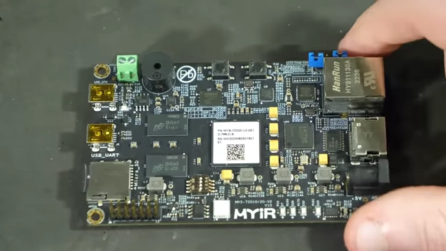
A close-up of the Zynq 7020 development board, the core of the controller [ 00:03:28 ] - FPGA's Role: The FPGA is crucial for versatility, allowing for on-the-fly rewiring of logic gates to create custom interface and processing modules.
-
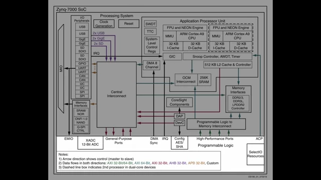
A detailed block diagram illustrating the Zynq-7000 SoC architecture, showing the processing system and programmable logic components [ 00:03:35 ] - These modules perform specific tasks, such as reading proprietary data from motor encoders or communicating with servo drives.
- The programmable nature of FPGAs enables support for virtually any device or interface without significant hardware changes.
-
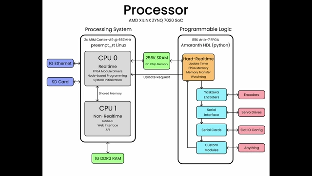
A block diagram illustrating the Zynq 7020 processor architecture with both processing system and programmable logic components [ 00:03:50 ] -
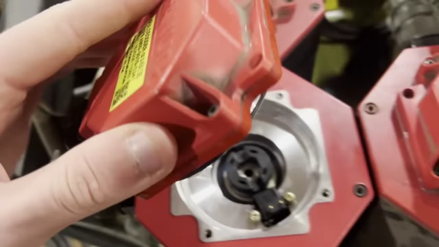
An encoder component from the back of a motor [ 00:04:02 ] -
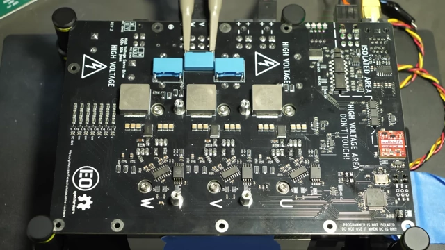
A custom servo drive circuit board on a workbench [ 00:04:05 ]
-
- Data Transfer Speeds:
- The main CPU updates software at 1,000 times per second (1 kHz), which is sufficient for robot operation.
- FPGA data transfers occur at 100 million times per second, allowing for extensive processing within a single software update cycle and enabling faster control loops directly on the FPGA if needed.
-
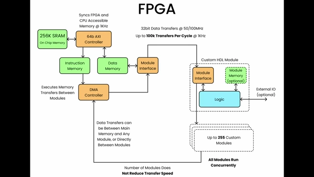
A block diagram illustrating the FPGA's internal data transfer speeds and module interactions [ 00:04:43 ]
- Backplane and Interface Cards: The Zynq is mounted on a custom backplane providing power and FPGA pins to four slots.
-
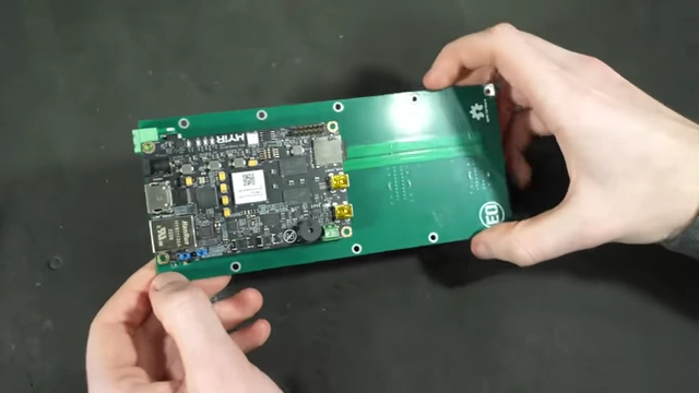
A person holding the custom backplane with the Zynq board attached [ 00:04:55 ] - Currently, serial interface cards support up to 10 RS485 or RS422 connections, covering a wide range of industrial protocols.
-
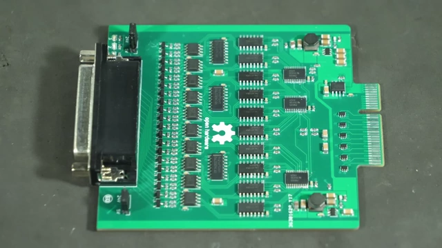
A custom serial interface card with multiple RS485/RS422 transceivers [ 00:05:04 ] -
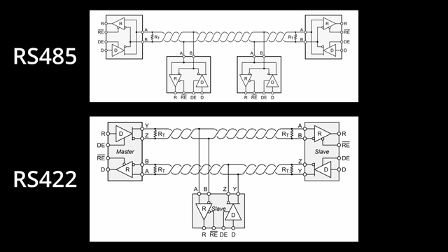
A diagram illustrating the RS485 and RS422 communication protocols [ 00:05:15 ] - Each motor connects to a servo drive, which powers the motor and regulates torque, while the Zynq handles velocity and position control.
-
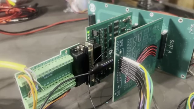
A close-up of a custom serial interface card connected to the backplane [ 00:05:23 ] -
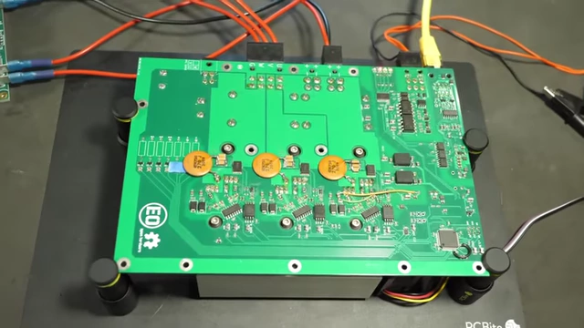
An assembled servo drive circuit board [ 00:05:26 ] -
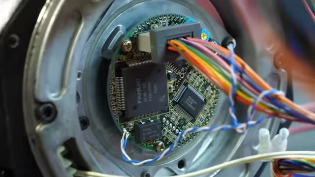
A close-up of a robot motor's encoder board [ 00:05:28 ]
-
Building the Controller [05:36]
The controller's physical construction involved careful planning and custom components.
- 3D Modeling: 3D models were created for all components to ensure a compact and efficient layout within the enclosure, facilitating precise screw hole and cutout placement via CNC machining.
-
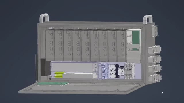
A 3D rendering of the controller's internal layout, showing multiple servo drives and other components tightly packed [ 00:05:50 ]
-
- Servo Drive Assembly: Ten custom servo drives were assembled, including fabricating heat sinks by cutting, milling, and threading aluminum to attach to the circuit boards. Loctite was used for added security.
-
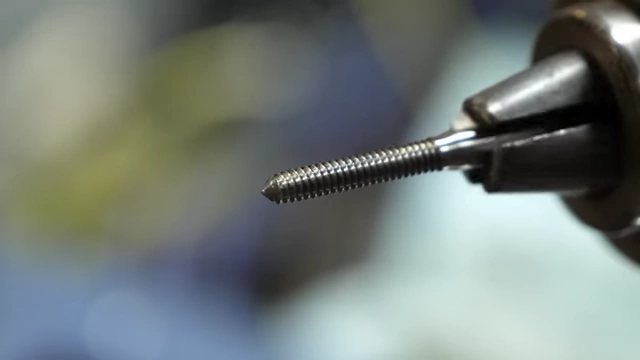
A form tap tool, used for creating threads in metal [ 00:06:47 ]
-
- Deadline for OpenSauce: The project was submitted as an exhibit for OpenSauce, setting a 3-month deadline to complete and ship the controller for a multi-day public demonstration.
-
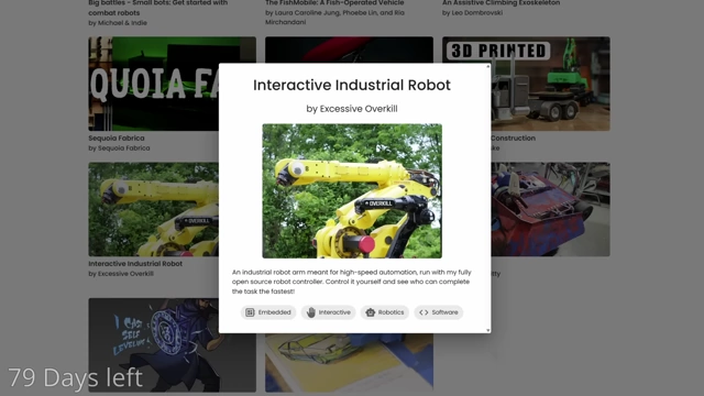
A screenshot of the OpenSauce exhibit submission page showing an "Interactive Industrial Robot" [ 00:07:25 ]
-
- Additional Boards:
- Isolation/Communication Modules: Small boards isolating and breaking out microcontroller pins for connecting other devices to the Zynq.
-
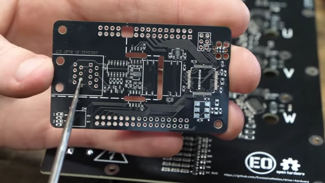
A small custom isolation and communication module board [ 00:07:34 ]
-
- E-stop Board: Handles safety-critical functions like main power to drives and motor brake release.
-
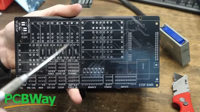
A custom E-stop board with multiple relays and terminal blocks [ 00:06:17 ]
-
- Encoder Adapter Board: A simple breakout board for connections from serial interface cards.
-
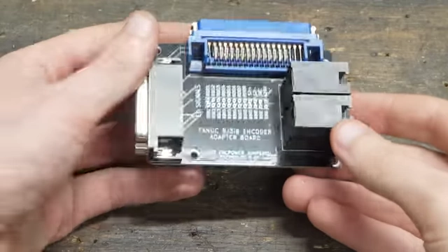
A custom encoder adapter board with a blue industrial connector [ 00:08:01 ]
-
- Isolation/Communication Modules: Small boards isolating and breaking out microcontroller pins for connecting other devices to the Zynq.
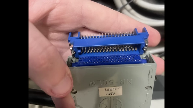
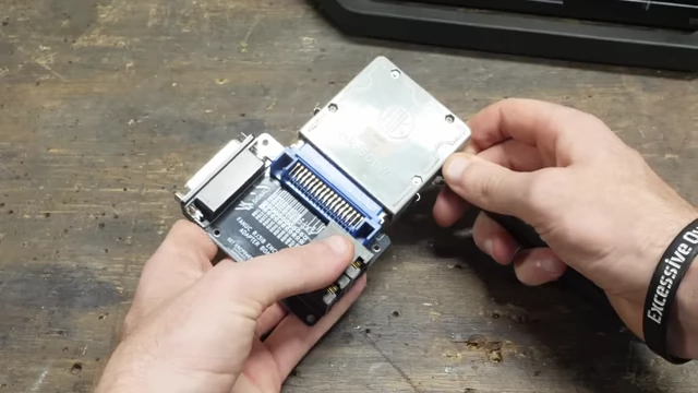
- Custom Robot Connectors: Sourced obsolete blue connectors from eBay to allow direct plug-and-play with the robot's existing cables, improving convenience.
Another Robot [08:26]
Due to the immense size and shipping costs of the 3,000lb Fanuc R2000 robot, a smaller alternative was chosen for the OpenSauce event.
- Fanuc R2000 robot: Label showing its weight (1240kg or ~2734lbs).
-
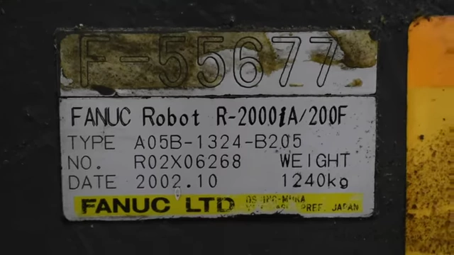
A close-up of the Fanuc R-2000 robot nameplate showing its weight in kilograms [ 00:08:31 ]
-
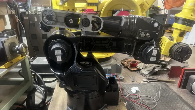
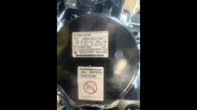
- Yasawa Motoman UP6: A 300lb robot with a 13lb payload, acquired for approximately $300 without a controller. It was disassembled, repainted, and chosen for its more manageable size for shipping.
Decoding Encoders [09:01]
A significant challenge with the Yasawa Motoman UP6 was deciphering its proprietary encoder protocol.
- Lack of Documentation: No information was available online for the Motoman encoders.
-
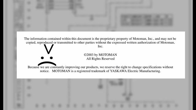
The cover of a Motoman XRC Controller UP6 Manipulator Manual, with a proprietary information warning [ 00:09:26 ]
-
- Request-Response System: Initial attempts to read constant position data failed, suggesting a request-response protocol where the controller must send a signal to trigger an encoder response.
-

A diagram illustrating the difference between a physical layer (RS485 schematic) and a data protocol [ 00:09:39 ] -
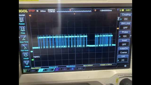
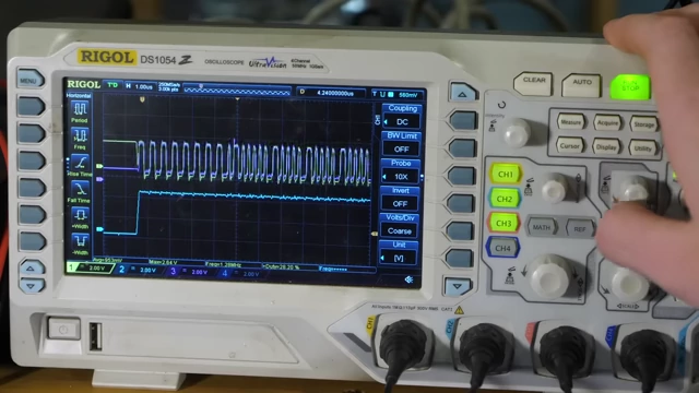
An oscilloscope screen displaying a complex waveform of encoder data [ 00:09:16 ] -
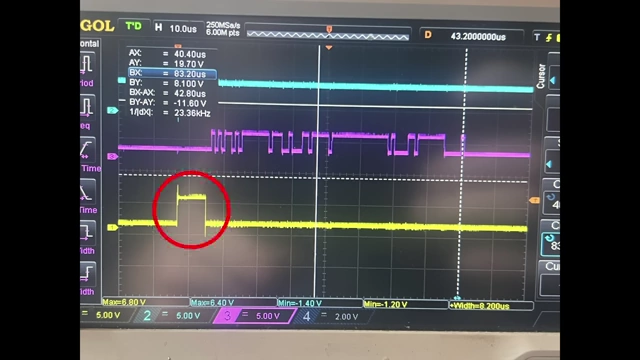
An oscilloscope screen showing a pulse, representing a failed attempt to trigger an encoder response [ 00:10:24 ]
-
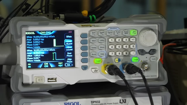
- Community Assistance: With help from a Discord community member who provided scope images of a working controller's signal lines, the request signal was emulated using a function generator.
- Data Decoding: After days of decoding the encoder's response, the data structure and reading method were largely figured out.
-
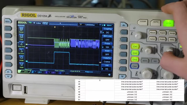
An oscilloscope displaying the encoder's response data after a request signal [ 00:10:58 ]
-
- FPGA Module: A new FPGA module was written to handle sending the request signal and decoding the response, enabling support for this new encoder type.

More Assembly [11:16]
Further assembly of the controller involved protecting components and integrating power systems.
- Enclosure Fit: A mockup confirmed that all components would fit, albeit tightly, within the chosen enclosure.
-
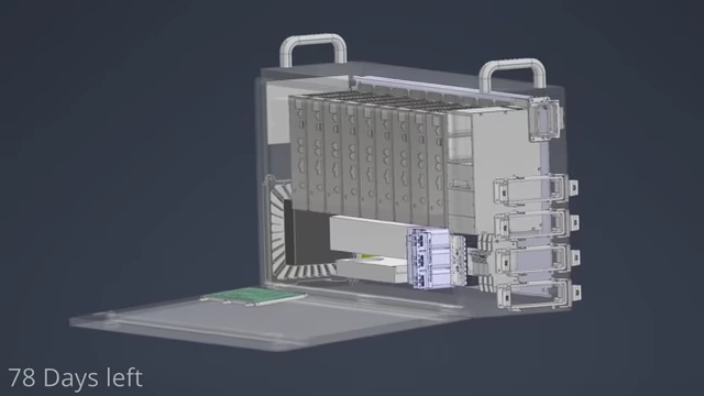
A 3D rendering of the controller enclosure with internal components and a "78 Days left" countdown [ 00:11:24 ]
-
- Main Components Installation:
- A line reactor (large inductor) to filter input power for the PFC drive and two large brake resistors.
-
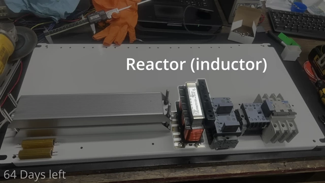
A line reactor (inductor) and brake resistors mounted on the controller's backplate [ 00:12:12 ]
- Nine Servo Drives: Nine drives were installed: six for the robot, one for PFC and brake resistors, and two for auxiliary motors.
-
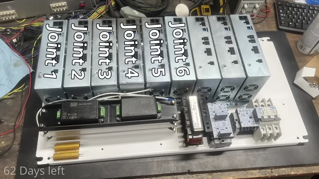
The back mounting plate of the controller with nine servo drives screwed down, labeled by their respective joints [ 00:12:42 ]
-
- Wiring: The wiring process was extensive, involving crimping numerous Molex connectors for motor phases and DC power jumpers between drives.
6D Mouse [14:46]
To provide intuitive control for event attendees, a 6D mouse was adapted.
- Acquisition: A defunct robotics company's closure allowed for the acquisition of this 3D mouse.
- It tracks movement and angle in 6 dimensions.
-

A close-up of the mechanical joints and encoders of the 6D mouse [ 00:15:19 ]
- Refurbishment: The original, old FPGA inside the mouse failed.
-
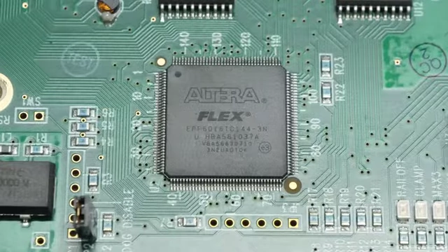
A close-up of an Altera FPGA chip on the 6D mouse's circuit board [ 00:15:40 ]
-
- Integration: The microcontroller sent data via a serial port, which was visualized with a Python program. Another custom serial module allowed communication with the main robot controller.
- Intuitive Control: The mouse's 3D position is mapped directly to the robot's movements, creating a "click and drag" interface for the robot.
Infinite Rotation Upgrade [16:20]
The robot's J4 joint, which rotates the arm's end section, originally had wires limiting it to +/- 180 degrees. This was upgraded for continuous rotation.
- Slip Rings: Slip rings, acquired from the same defunct robotics company, were installed.
- These devices transmit electrical signals through a rotating joint.
-
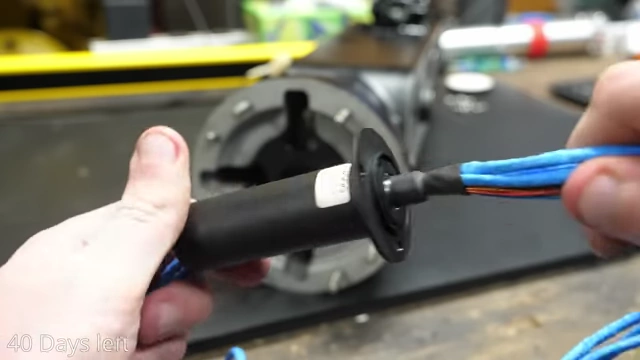
A slip ring, which allows electrical signals to pass through a rotating joint [ 00:16:49 ]
Making Robot Cables [17:25]
The robot lacked connecting cables, so new ones were fabricated.
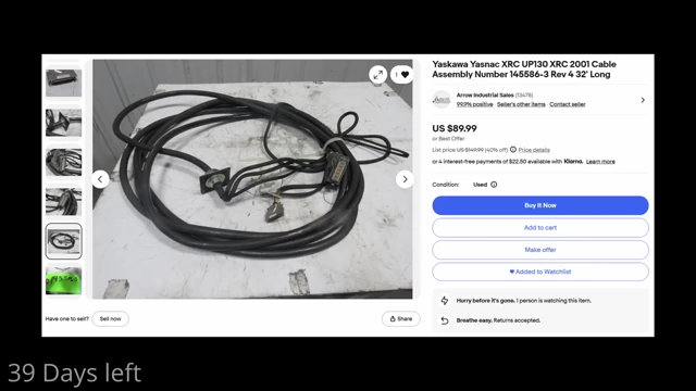
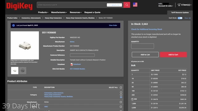
- Cost-Effective Solution: Instead of expensive original cables found on eBay, inserts and contacts were purchased from DigiKey.
- 3D Printed Housings: Custom housings were 3D printed to hold the smaller, six-pin connectors together and clamp onto the robot's receptacles.
Software and Programming [18:20]
The controller's software stack comprises around 30,000 lines of code.
- Node-Based Programming: The primary interface is a combination of node programming and ladder logic, allowing for editing at runtime (though not yet fully implemented).
- It aims for a user-friendly approach similar to LinuxCNC's Hardware Abstraction Layer (HAL) but with a more defined and understandable setup.
-
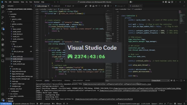
A screenshot of Visual Studio Code showing extensive lines of code, with a timer indicating over 2374 hours of development time [ 00:18:29 ] -
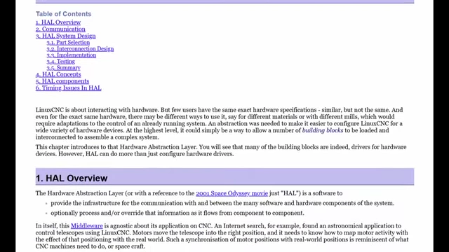
A screenshot of documentation describing the Hardware Abstraction Layer (HAL) in LinuxCNC [ 00:18:49 ] -
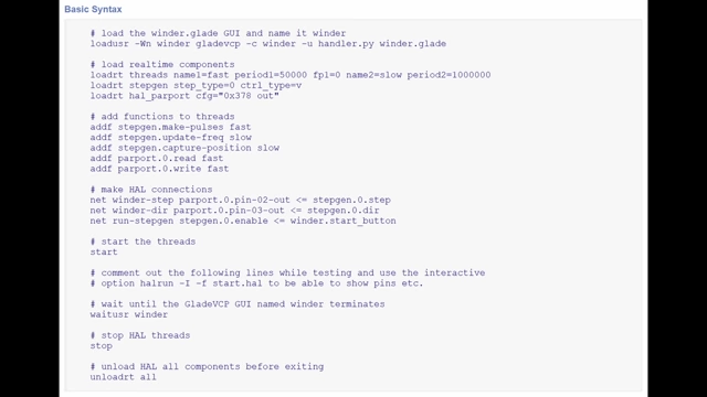
A screenshot displaying basic syntax for LinuxCNC configuration [ 00:18:53 ] -
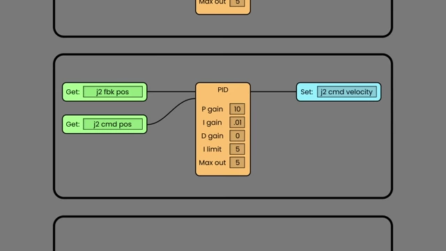
A node-based program interface showing a PID control loop [ 00:19:05 ] -
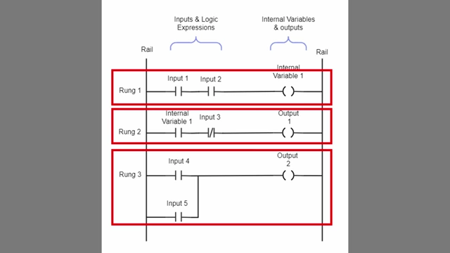
A diagram illustrating ladder logic with rungs, inputs, and outputs [ 00:19:16 ] -
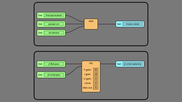
Two examples of node networks for robot control, including an AND logic gate and a PID controller [ 00:19:22 ]
- Optimal Order: The program determines the optimal execution order of nodes at startup, starting from inputs and stepping down the chain, preventing accidental loops.
- Device Descriptor Files: Each connected device (drives, serial modules) has a descriptor file defining its type, versions, constants, and crucial communication variables.
- A Python script compiles this data into C++ code for firmware and generates a file specifying variables accessible to the controller.
-
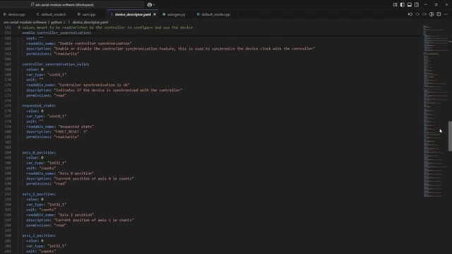
A screenshot of a YAML device descriptor file defining communication variables [ 00:20:13 ]
Kinematics [20:44]
Kinematics is essential for commanding the robot to reach specific positions in space.
-

A text overlay stating "Inverse Kinematics" [ 00:21:36 ] - Inverse Kinematics: This is the more complex problem of calculating the required joint angles to achieve a desired end-effector position.
-
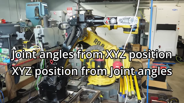
Text explaining the concepts of calculating joint angles from XYZ position and vice versa [ 00:21:45 ] - An iterative solver is used, starting from the robot's current position and taking small steps towards the target until it's close enough or out of reach.
-
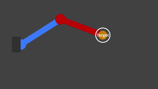
An animated diagram showing a two-segment robot arm moving iteratively towards a target point [ 00:22:08 ]
-
- Performance Optimization: Written in C++ for speed, the kinematics calculations still ran slow until compiler optimization was enabled, providing a 10x speed boost and allowing operation at 1 kHz.
- Joint Limit and Mixing: Code was added to keep the robot within joint limits and to "mix" the joints, compensating for dependencies where one joint's movement affects another (e.g., J6 gearing running through J5).
-
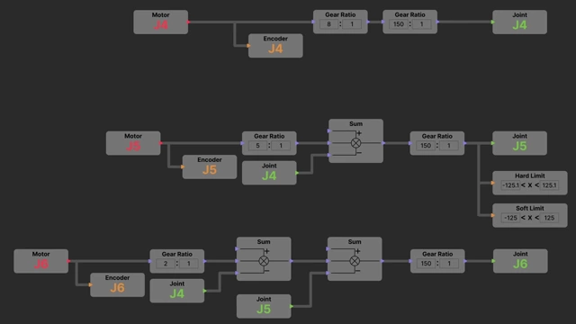
A node diagram showing the mixing logic for robot joints J4, J5, and J6 [ 00:21:13 ]
-
It Works! [23:17]
With kinematics integrated, the robot became fully controllable.
- XYZ Control: The robot can now be jogged in XYZ space, rather than just by individual joint angles.
- 3D Mouse Control: Inverse kinematics was also applied to the 3D mouse. Instead of direct joint mapping, the mouse's end XYZ position commands the robot's end position, acting as an intuitive "click and drag" interface.
- This control method was found to be very engaging and surprisingly precise.
-
The robot arm, controlled by the 3D mouse, precisely manipulates a colorful foam block [ 00:23:18 ]
- Practical Application: While writing or signing names proved difficult due to the lack of force feedback, picking up and moving objects (like foam blocks) was remarkably easy to learn and execute.
Power Supply Issues [24:18]
Testing revealed significant challenges with the power factor correction (PFC) drive.
- Pre-charge Resistor Impact: Suspected issues with overly large pre-charge resistors and the drive's slow adjustment to sudden resistance changes during contactor switching led to voltage spikes.
-
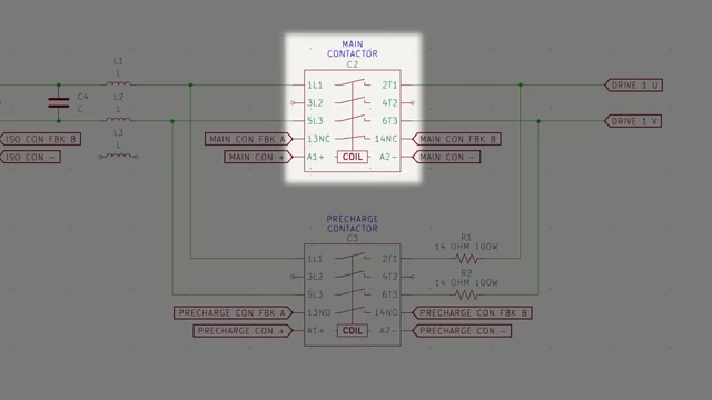
A schematic diagram highlighting the main contactor in the power supply circuit [ 00:27:13 ]
-
- Phase Current Sense Imbalance Errors: The PFC drive began throwing errors indicating current imbalance, similar to a GFCI.
- MOSFET Explosion: Eventually, a MOSFET on one of the drives exploded due to an arc from its tab to the grounded heat sink.
- This was attributed to inadequate dielectric properties of the thermal paste used, which failed at higher voltages despite ceramic insulators.
-
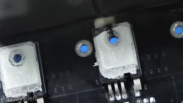
A close-up of a damaged MOSFET on a circuit board, showing an arc mark and residue [ 00:29:07 ]
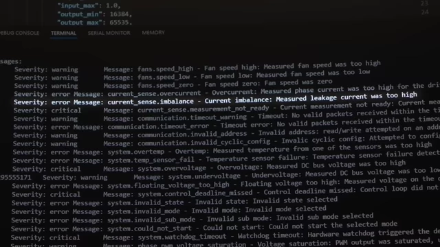
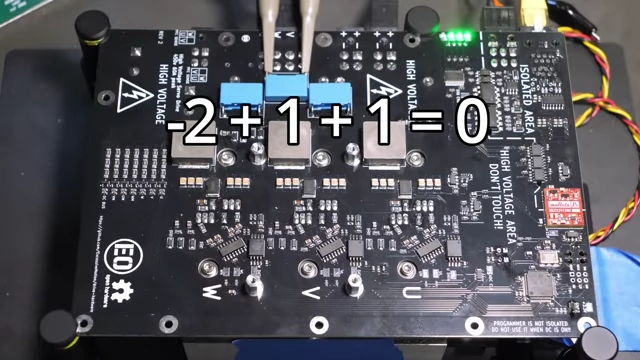
Drive Issues [30:15]
Further testing uncovered problems with the individual motor drives.
- Crunching Noise (J2 Drive): The J2 drive developed a crunching noise, progressively worsening to the point where the motor barely moved when powered.
- Underrated Inductors: Investigation revealed that the main output filter inductors in the drives were rated for only 75 volts, significantly lower than the 100-200+ volts being applied during testing.
- This voltage mismatch likely caused internal arcing, leading to the crunching noise, current sensing errors, and poor motor control.
-
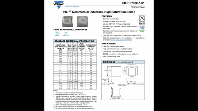
A datasheet for "Commercial Inductors, High Saturation Series," showing a maximum rated voltage of 75V [ 00:31:07 ]
- Temporary Solution: Given the limited time before the Open Sauce event, the creator opted to run the system at a lower voltage (36V input, boosted to 60V by the PFC drive) to avoid the drive issues, deferring a full fix for later.
Safety [31:48]
Safety was a critical concern, especially for public interaction with the robot.
- ESTOP Board: This board handles all critical safety functions.
- Two-Channel Wiring: The E-stop system uses redundant, two-channel safety circuits, ensuring that a single point of failure (e.g., a damaged wire) does not compromise safety.
-
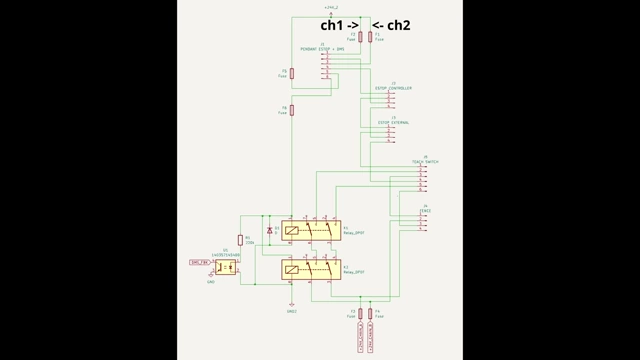
A schematic diagram of the E-stop circuit, showing two channels for safety [ 00:32:21 ]
-
- Hardware-Based Safety: Critical functions operate solely through redundant relays, with no software involvement to maximize reliability.
- Microcontroller Checks: The microcontroller performs constant checks to ensure components are in their correct on/off states, shutting down the system if any anomaly is detected (e.g., stuck relays, manual power jumps).
- Safety Zone with Laser Scanners:
- Laser scanners were used over light curtains due to easier setup and configuration.
- They create vertical safety walls around the robot area. If anything breaks these laser beams, the system triggers a stop.
-
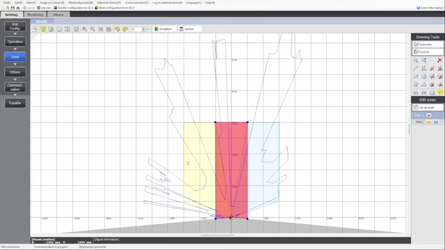
The configuration software for a laser scanner, showing a grid with defined safety zones (red and yellow areas) [ 00:33:37 ] - These are fully safety-rated industrial devices (costing around $3,000 new), designed with redundant processing to protect people from machinery.
- Bypass Function: An issue was identified where the robot could get stuck in the safety zone, preventing restart. A bypass box with a specific button/switch sequence was implemented to temporarily disable scanners, allowing the robot to be moved out of the safety area. The bypass is time-limited to prevent accidental permanent disablement.
- Space constraints at the event: The layout of the event space, highlighting the challenge of setting up safety zones in a limited area.
-
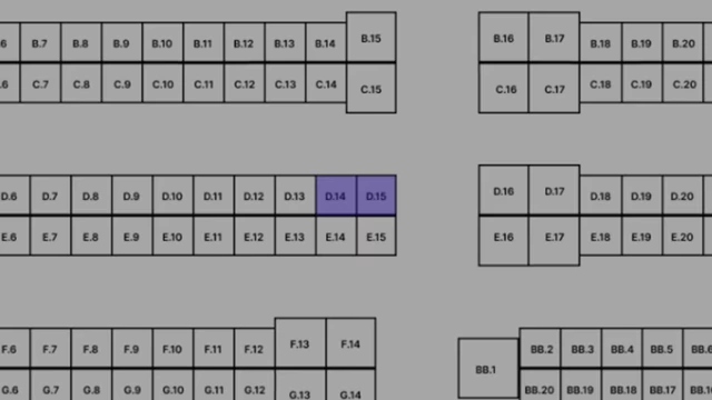
A floor plan of an event layout, showing an 8x6 ft exhibit space [ 00:33:01 ]
-
Open Sauce! [35:16]
The robot and its controller were successfully transported and exhibited at Open Sauce.
- Logistics: The 1200lb setup was packed into a single crate and shipped terminal-to-terminal to save costs and utilize forklifts.
- Event Setup: The system was unpacked and set up in an 8x6 ft space.
- Controller Performance: The custom controller performed flawlessly, running constantly without issues throughout the event.
- Public Interaction: Many attendees, including YouTube celebrities and even a surgeon familiar with Da Vinci robots, controlled the robot.
- Despite efforts, attempts at writing or signing names were difficult due to lack of force feedback.
- Stacking foam blocks proved to be a popular and successful interactive activity.
-
The robot and controller setup at the Open Sauce event, surrounded by attendees who are watching and interacting with the robot [ 00:36:27 ]
Whats next? [37:45]
The project is entirely open-source, with hardware and software files available on GitHub.
- The creator aims to make the system more accessible and user-friendly for wider adoption.
- A survey is provided to gather feedback and determine user interest for future development.
- Viewers are encouraged to support the project by engaging with the video (likes, shares) and considering direct donations or Patreon support to fund continued development.