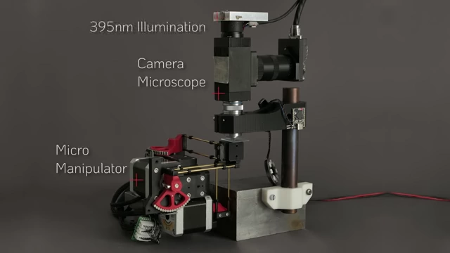
This video introduces an open-source, motorized XYZ micro-manipulator capable of sub-micrometer motion control.
The device improves upon a manual design, offering programmable paths, higher resolution, and faster speeds.
Key design elements include miniature ball joints, chosen for their stiffness and range of motion, preloaded with polyurethane rubber bands for stability.
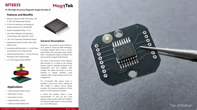
Precision motion is achieved using low-cost stepper motors driven by high-resolution PWM signals and enhanced with custom magnetic gearing for increased encoder resolution.
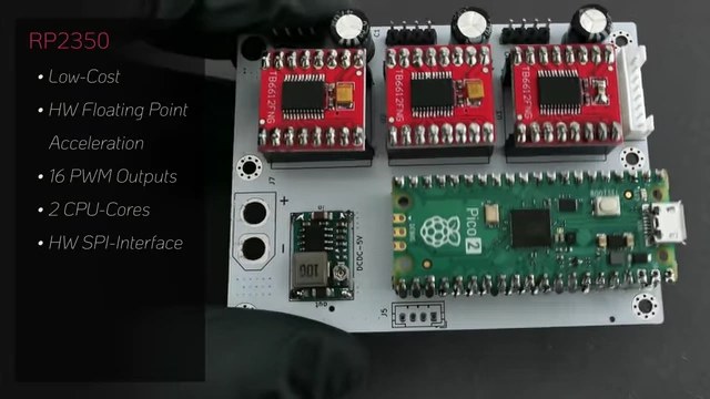
The electronics are built around an RP2350 microcontroller and TB6612 H-bridge drivers, ensuring stable and jitter-free operation.
The C++ firmware implements field-oriented control, inverse kinematics, and look-ahead motion planning, running servo loops on a dedicated CPU core.
Calibration of the magnetic encoders corrects for nonlinearities, enabling precise control.
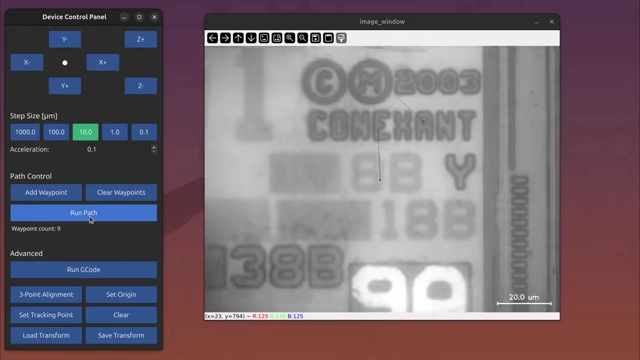
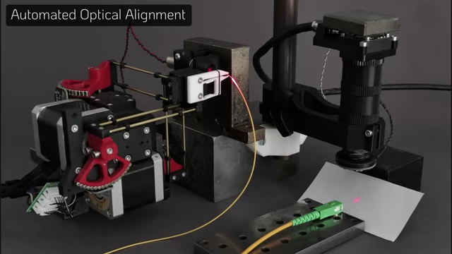
Applications include automated microscopy, demonstrated by tracing a microscopic "Benchy," and optical alignment for fiber coupling.
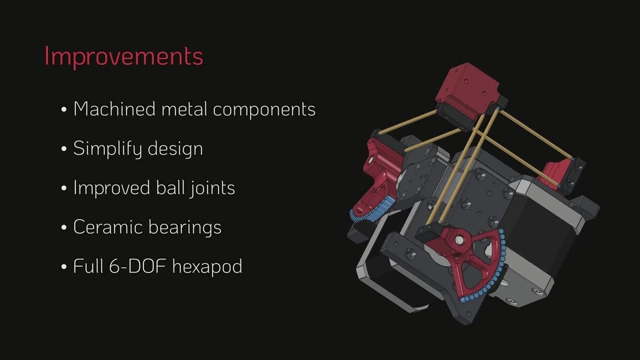
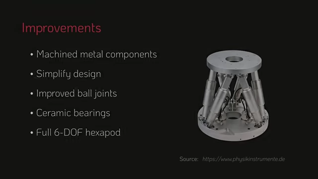
Future improvements include using machined metal components, ceramic bearings, and scaling up to a 6-DOF hexapod.
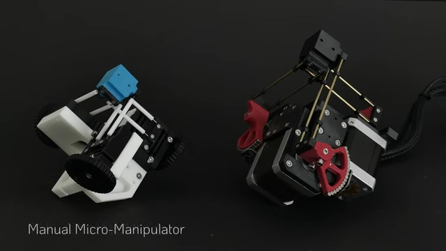
Comparison of the manual vs. automatic micro-manipulator
[
00:01:30
]
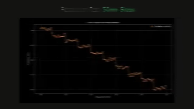
Graph demonstrating the precision of 50nm steps during a resolution test
[
00:22:47
]
Overview of the Motorized Micro-Manipulator [01:18]
Comparison of the manual vs. automatic micro-manipulator
[
00:01:30
]
The video presents a successor to a previously introduced 3D-printed manual micro-manipulator.
The new design is fully programmable, offering:
Higher resolution.
Faster speeds.
A larger working volume.
This motorized version enables a wide range of applications, some of which are demonstrated later in the video.
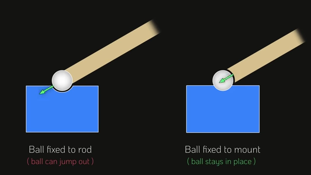
Diagram illustrating the advantage of fixing the ball to the mount for stability in ball joints
[
00:02:40
]
Miniature ball joints are a crucial design element, offering:
A much larger range of motion compared to flexures.
High stiffness.
The downside is non-zero friction, minimized by:
Choosing a small ball size relative to the connection rod length, creating large leverage.
Selecting suitable materials.
The ball is fixed to the mounts, and the joint socket is placed on the connection rods.
This orientation prevents the ball from jumping out under large joint angles, as parallel kinematic designs primarily produce forces in the direction of the rods.
The ball joints require preloading for bidirectional force transmission and structural integrity.
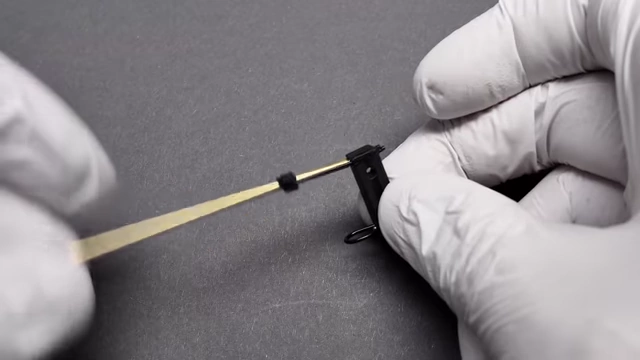
A small 1mm polyurethane rubber band (magic string) is used for this purpose due to its ability to maintain tension over time.
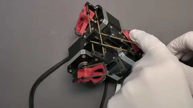
Each ball joint is preloaded individually and symmetrically for enhanced stability, preventing structural collapse seen with single-band preloading.
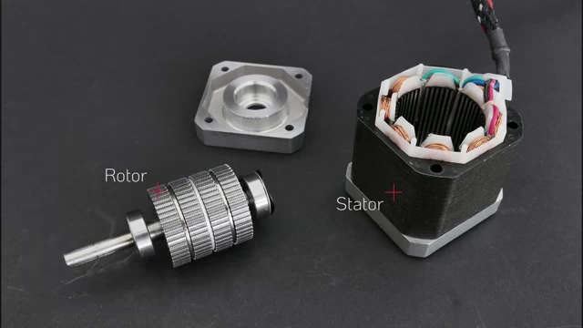
Disassembled Nema17 stepper motor showing the rotor and stator
[
00:04:50
]
Low-cost stepper motors are used, which can achieve high precision when driven correctly.
Achievable step sizes are around five arcseconds in open-loop operation, equivalent to approximately 2500 times micro-stepping, using a high-resolution PWM signal.
Mechanically, most stepper motors use ball bearings preloaded by a spring mechanism.
While preload is effective against play, standard ball bearings are not ideal for high-precision applications and are a potential source of error.
The stator contains significant iron, leading to magnetic hysteresis.
This means the magnetic field depends on both current and previous magnetization state, making accurate open-loop positioning difficult due to hysteresis and residual friction.
Closed-loop control is necessary for accurate positioning.
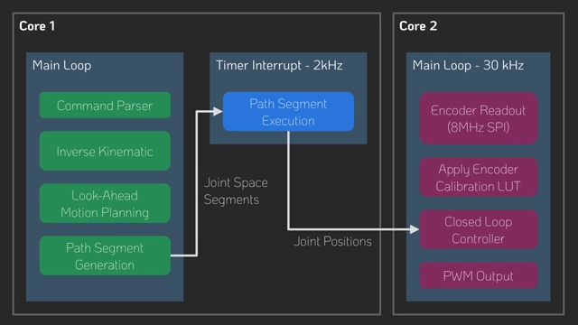
Firmware architecture diagram showing dual CPU core functions for servo loops and motion planning
[
00:10:50
]
The firmware is written in C++ for simplicity, readability, and performance.
Dual-core operation:
Core 2 handles servo loops for all three motors at 30 kHz for fast, responsive closed-loop control, including encoder readout, calibration, and PWM output.
Core 1 handles other tasks, including math-intensive inverse kinematics, command parsing, and motion planning.
Motion planning and execution:
Follows standard practices: motion commands are added to a queue as path segments.
Look-ahead planning sets start and end velocities to comply with acceleration constraints.
Each path segment is subdivided into linear joint space segments.
Inverse kinematics is evaluated at the start and end points of these segments in a 2 kHz timer interrupt function.
Joint space segments are interpolated and executed, with joint positions passed to the servo loops.
Encoder calibration:
The magnetic encoder setup introduces nonlinearities, requiring calibration.
Calibration is performed during the homing sequence, aligning the electric field with the encoder angle.
This method assumes the rotor perfectly follows the field, which is adequate for applications not requiring high absolute accuracy.
The calibration generates a lookup table (LUT) to correct raw encoder counts.
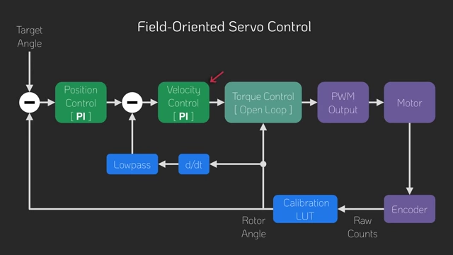
Field-Oriented Servo Control:
Block diagram illustrating the Field-Oriented Servo Control system
[
00:12:22
]
Uses a cascaded control scheme: a position controller determines target velocity, which a velocity controller uses for target torque.
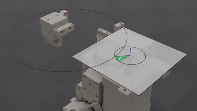
Torque command is converted to an electric field angle offset and added to the measured rotor position.
Without current sensing, the electric field angle directly translates to coil voltages for PWM outputs.
Velocity feedback is derived from the low-pass filtered derivative of the rotor position.
Closed-loop control significantly improves precision and stiffness compared to open-loop control.