DIY Photochemical Machining: Creating Precise Sheet Metal Parts at Home
- The video demonstrates a detailed DIY photochemical machining process, offering a cost-effective alternative to commercial services for producing precise, fine-featured sheet metal parts for prototyping or low-volume production.
- The initial steps involve rigorous cleaning of sheet metal using a hot water bath and a water break test to ensure optimal photoresist adhesion, followed by careful drying with shop towels.
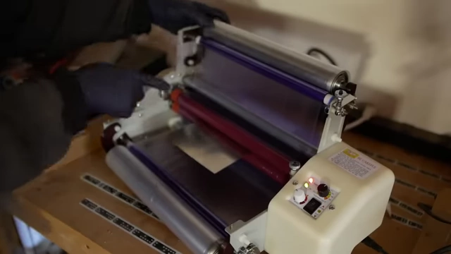
- Dry film photoresist is then laminated onto both sides of the cleaned metal using a customized laminator designed to correctly peel off the soft protective layer.
- High-contrast photomasks are printed on special transparencies using an inkjet printer with specific ink, and a practical trick is shown for printing on clear film.
- Masks are precisely aligned on the metal, ensuring the emulsion side is closest to the panel, and exposed to UV light from a custom rig built for sharp shadow resolution.
- After exposure, the protective layers are removed, and the photoresist is developed in a sodium carbonate solution, revealing the pattern.
- The metal undergoes spray etching in a custom machine with a high-pressure pneumatic pump and ferric chloride, enabling efficient, faster etching where parts fall freely into a mesh bag.
- The final step, though not fully demonstrated, involves stripping the remaining photoresist with a strong basic solution.

Various precise metal parts created using the photochemical machining process, including a ring, a solid circle, a fan-like design, and a multi-fingered component. [ 00:21:27 ]
Introduction to Photochemical Etching [0:00]
The video introduces photochemical machining as a method for creating precise sheet metal parts with features too fine for traditional methods like water jet or laser cutting, or for designs with a high density of holes, such as meshes.


- Problem with Traditional Methods:
- Water jets and laser cutters can distort fine features.
- Large number of holes makes cutting impractical or impossible.
- Commercial Vendor Limitations:
- High costs: Approximately $300 setup fee and $600 minimum for 10-20 parts.
- Long lead times and slow iteration process.
- Motivation for DIY:
- Cost-effective for prototyping and low-volume production.
- Enables faster design iteration and experimentation.
- Personal interest in tinkering and exploring a potential side business.
Why Use Photochemical Etching? [1:39]
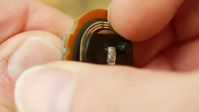
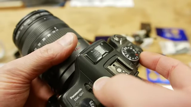
Photochemical etching is crucial for applications requiring very fine or complex features that cannot be achieved by stamping, laser cutting, or water jet cutting.

- Common Applications:
- Battery terminals, potentiometer wipers, micro switch spring fingers.
- Grilles for microphones or speakers in electronics.
- Components for battery doors and drone parts.
- Limitations of Stamping:
- Primarily suited for high production volumes.
- Expensive for low production volumes or prototyping due to die creation costs.
- Unique Capabilities of Photochemical Etching:
- The only viable method for creating custom mesh patterns with specific sizes or opacities.
- Allows for complex, intricate designs that other methods cannot replicate without distortion or immense cost.
Optimizing for Cost and Automation [3:00]
The video proposes strategies to reduce the cost and manual labor associated with photochemical etching, making it more accessible.
- Automated Part Separation:
- Traditional parts are held by tabs and require manual cutting and deburring.
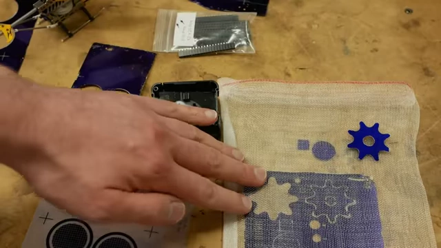
- Innovation: Etching parts while contained in a mesh bag allows them to fall free from the panel during the etching process.
- Eliminates manual handling, counting, and quality control checks, simplifying the finishing process for the customer.
- Automated Artwork Generation:
- Current commercial photochemical suppliers often require emailing artwork, leading to slow back-and-forth with layout engineers.
- Proposal: Implement an automated artwork upload system, similar to CNC machining, multi-layer PCBs, or laser/water jet cutting services.
- This would provide real-time pricing and timelines, saving time for both the business and the customer.
- Example: Flip Pins:
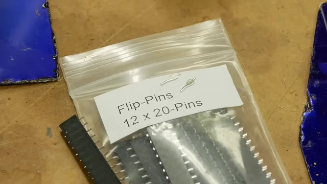
- Niche products like "flip pins" (DIP-sized pins for breadboards) are ideally suited for photochemical etching due to their low production volume needs, where stamping would be too expensive.
Sheet Metal Cleaning for Optimal Adhesion [5:37]
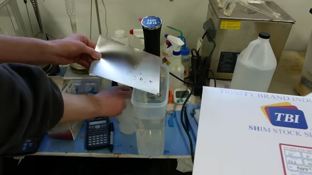
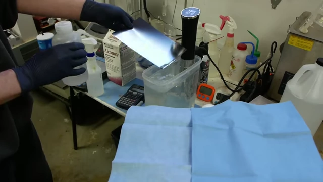
Thorough cleaning of the sheet metal is the critical first step to ensure proper adhesion of the photoresist.

- Material Cost:
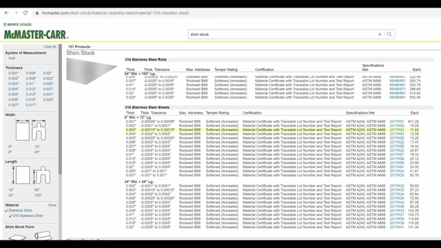
- Sheet metal (e.g., from McMaster-Carr) is a relatively inexpensive component of the process, typically costing $5-10 per sheet.
- Cleaning Process:
- Water Break Test: Essential for verifying cleanliness. Water beading up indicates oil contamination; water sheeting off evenly signifies a clean surface.
- Immersion Cleaning: Metal is immersed in a heated solution (e.g., water and alcohol, or sodium hydroxide) using a sous-vide cooker to maintain temperature.
- Rinsing: After cleaning, the metal is thoroughly rinsed with deionized water.
- Drying: The best method is to scrub the metal dry with shop towels, as air drying or compressed air can recontaminate the surface with oil droplets.
Applying Dry Film Photoresist [8:19]
The photoresist, a light-sensitive polymer, is applied to the cleaned metal using a laminator.
- Photoresist Composition:
- Dry film photoresist consists of three layers: a soft protective layer, the photoresist itself, and a hard protective layer.
- Laminator Modification:
- Cheap commercial laminators are not designed for this.
- The laminator needs modifications (e.g., spring-loaded take-up spools) to peel off the soft protective layer as the photoresist is applied to the metal.
- Lamination Settings:
- Temperature: Approximately 110°C.
- Speed: Very slow to ensure proper adhesion and removal of the soft layer.
- Result: The metal comes out with photoresist firmly laminated on both sides, protected by the hard outer layers.
Creating High-Contrast Photomasks [10:44]
High-quality photomasks are essential for achieving sharp, high-resolution etched patterns.
- Printer Choice:
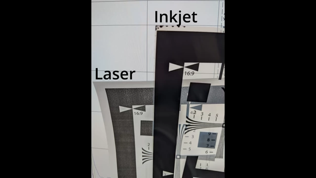
- Laser Printers are Unsuitable: They produce toner images with pinholes and insufficient density, leading to poor contrast.
- Inkjet Printers are Recommended: They can achieve superior contrast.
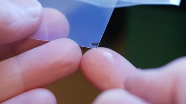
- Specialized Materials: Use special ink and transparencies with an emulsion coating (e.g., from FilmDirectOnline) that absorbs and holds a large amount of ink without smudging.
- Printing Process:
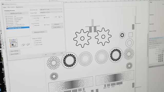
- Printer settings are dialed up to dispense the maximum amount of ink for maximum contrast.
- Dual Masks: Two masks are printed side-by-side on the same sheet. This ensures any minor stretching along the printer rollers affects both masks identically, preserving registration for double-sided etching.
- Printer Quirk Solution: If a printer's optical sensor fails to detect clear transparencies, placing a white piece of paper underneath can trick it into printing.
Precisely Aligning and Exposing the Masks [12:50]
Accurate alignment and controlled exposure are crucial for transferring the design onto the photoresist.


- Mask Alignment:
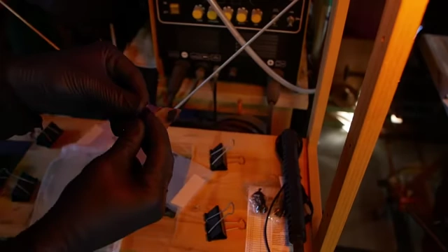
- The two printed masks are aligned precisely, emulsion side facing the metal panel, and secured with double-sided tape.
- "Book" Method Avoidance: A hinged "book" method (tape on one side) is avoided because the thickness of the metal can introduce slight registration errors. Taping both sides ensures consistent, symmetric alignment.
- Exposure Setup:
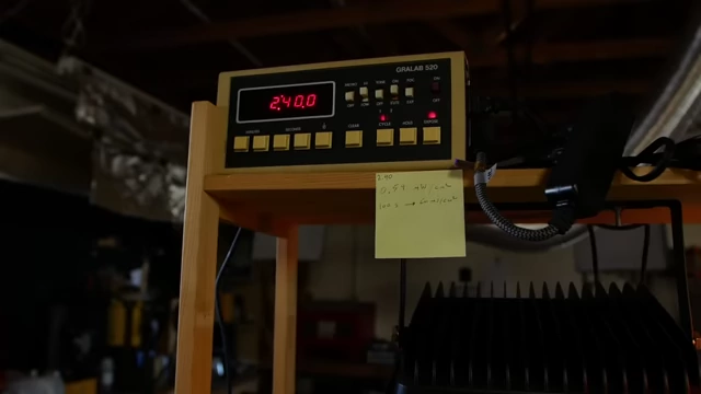
- A custom exposure rig is used, featuring two 150W 405nm floodlights.
- Light Source Distance: Lights are placed far from the artwork to create sharper shadows, preventing UV light from "sneaking" under dark areas and ruining resolution.
- Exposure Parameters:
- Measured light intensity: Approximately 0.5 milliwatts per square centimeter (mW/cm²).
- Practical exposure time: 2 minutes 40 seconds.
- Note: Commercial datasheets typically suggest a dose of 60 millijoules per square centimeter (mJ/cm²), which would translate to about 100 seconds, indicating some non-idealities in the DIY setup.
- Pre-Development Step: Before developing, the hard plastic protective layers are carefully peeled off the photoresist to expose the light-activated material.
Developing the Photoresist Pattern [16:01]
The exposed photoresist is developed to reveal the etched pattern.
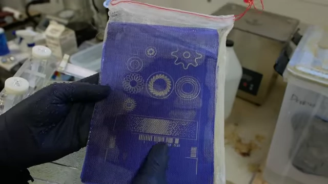
- Developer Solution:
- A simple solution of tap water and sodium carbonate.
- Development Machine:
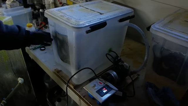
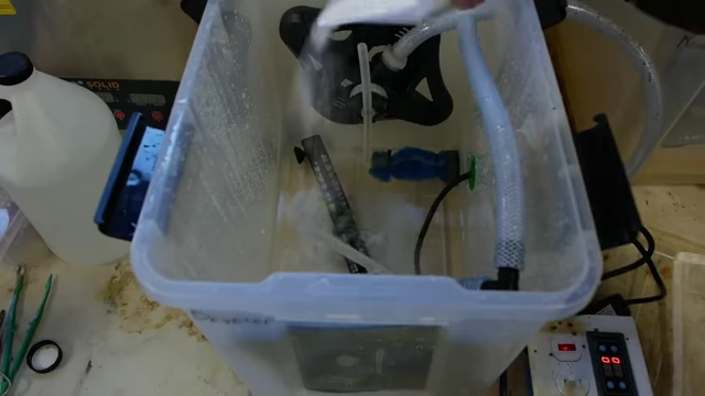
- A plastic tub equipped with spinning sprinklers, an external pump, a timer, and a heater to maintain the solution temperature at approximately 28°C.
- The metal panel, now in a mesh bag and loaded into a carrier, is placed in the developer tank.
- Development Time:
- Approximately 70 seconds.
- Rinsing: After development, the panel is rinsed (typically in a dedicated rinse tank, but a hose was used for demonstration).
- Quality Check: The developed pattern is inspected for good registration and resolution, ensuring the photoresist has been properly removed in the unexposed areas.
Etching the Metal with a High-Power System [17:04]
The developed metal is then etched using a powerful spray etcher.
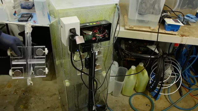
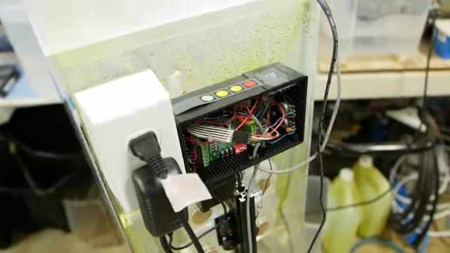
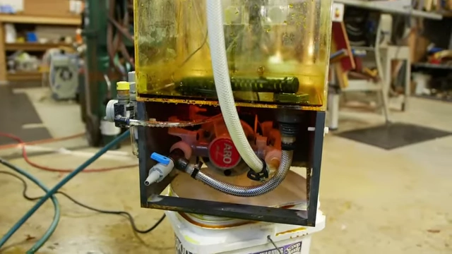
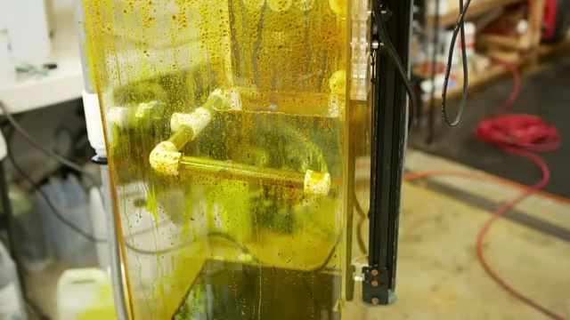
- Etcher Holder Design:
- A specialized holder with rollers and plastic-encased magnets allows for "through-the-wall" movement within the etching tank.
- This design eliminates the need for tank penetrations, simplifies loading/unloading, and keeps the panel in precise registration.
- Actuator System:
- A linear belt drive actuator (e.g., from OpenBuilds) powered by a stepper motor and controlled by a Teensy microcontroller, featuring a display and user interface.
- This system also controls the heater and etching time.
- Etchant Pump and Flow:
- A high-pressure, high-flow Aro pneumatically powered pump is essential.
- Spray Etching vs. Immersion: Spray etching is about 10 times faster than simple immersion or even stirred etching. The force of the spray efficiently removes etch products, accelerating the process.
- The pump's pulsatile output is cushioned by an "air hammer" mechanism.
- Material Compatibility:
- Finding plastics compatible with hot ferric chloride is challenging. Nylon and Delrin are unsuitable, and even polypropylene can fail, leading to dangerous leaks.
- Etching in a Mesh Bag: The panel is etched inside a mesh bag, which allows the completed parts to fall freely from the main sheet, streamlining the finishing process.
Stripping the Photoresist [20:40]
The final step involves removing the remaining photoresist from the etched parts.
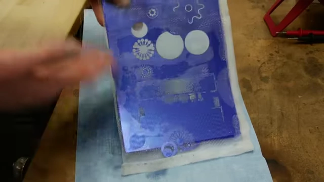
- Stripping Solution:
- A strong basic solution, such as sodium hydroxide or potassium hydroxide, is used to strip the photoresist.
- Mechanism:
- The photoresist does not dissolve but rather comes off in large chunks.
- Previous System: A flow cell was previously used to facilitate the removal of these photoresist chips from the mesh bag, but it was not available for the demonstration.
Final Results and Troubleshooting [21:22]
The video concludes with a review of the etched parts and a brief acknowledgment of challenges.
- Outcome: The parts turned out "kind of okay," but the presenter notes it wasn't his best work.
- Challenges Encountered: A major problem with the etching machine required pausing the process midway, which negatively impacted the final quality. The equipment had not been used recently.