Advanced VIC-II Programming: A Comprehensive Guide to C64 Demo Effects
FairLight - Home of the Real Crackers
Summary:
This video offers a comprehensive guide to advanced programming techniques for the Commodore 64's VIC-II chip, essential for aspiring demo coders. Key topics include:
- An introduction to the "Holy Trinity" behind the C64's hardware (Al Carpentier, Bob Giannis, Chuck Pedal).
- Defining fundamental terms like "raster line," "horizontal blank," and "vertical blank," and understanding VIC register behavior.
- Detailed explanations of "bad lines" and their impact on CPU cycles.
- Exploration of advanced graphic effects, including multi-layered sprites, Flexible Line Distance (FLD), and Line Crunch.
- Deep dives into Virtual Screen Position (VSP), Any Given Screen Position (AGSP), and Flexible Line Interlace (FLI) for complex visual manipulations.
- Insights into sprite-specific tricks like "Dough Hook" and "Sprite Crunch," showcasing how to manipulate sprite pointers and displays for unique visual outcomes.

Important VIC registers and their functions for C64 programming [ 00:15:50 ] 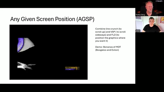
Any Given Screen Position (AGSP) combines line crunch, VSP, and FLD for full-screen graphics movement [ 01:10:01 ]
Introduction to C64 Demos and VIC-II Chip [0:09]
- The video aims to provide a complete guide to key techniques used in Commodore 64 (C64) demos, focusing on the VIC-II chip.
- It is designed for aspiring C64 demo coders, explaining how complex demo effects are achieved.
- Adam "Trident" Dunkels joins as a co-presenter to help explain these techniques through a detailed presentation.
Key C64 Figures (The Holy Trinity) [02:47]
![The Holy Trinity of the C64: Jack Tramiel, Al Carpentier (VIC-II), and Chuck Peddle [<a href="https://youtube.com/watch?v=lLpXS6YiK3k&t=6502">6502</a>]](https://storage.googleapis.com/summarizer-images/images/lLpXS6YiK3k/sc0002_t00.04.30.webp)
- The C64's "Holy Trinity" comprises three pivotal figures:
- Jack Tramiel: CEO of Commodore Computer, who guided the company from typewriters and calculators into computers, with the C64 becoming their flagship product.
- Albert "Al" Carpentier: Creator of the VIC and VIC-II chips, crucial for C64 graphics. He also modified the 6502 into the 6510 and designed the 6526 CI chips.
- Robert "Bob" Yannes: Designer of the SID chip, responsible for the C64's iconic sound.
- These individuals were instrumental in the C64's creation, though many other contributors also played vital roles.
Defining Important Terms and Concepts [04:50]
- VIC-II Chip: The primary graphics chip in the C64, specifically the NTSC version (MOS 6567). Older versions had fewer luminance levels and different kernel behaviors.
- Screen Areas:
- Border: The area outside the main displayable screen.
- Screen: The main displayable area where graphics and text are usually rendered.
- Frame: The entire displayable area, encompassing both the screen and its borders.
- CPU-VIC Synchronization:
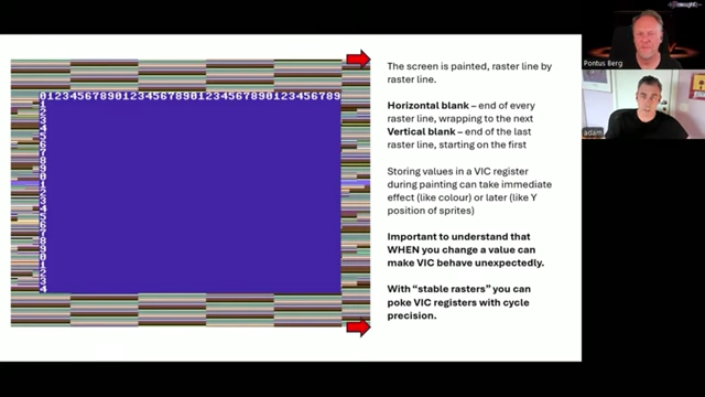
Diagram illustrating how the C64 screen is painted raster line by raster line, and the immediate vs. delayed effect of VIC register changes [ 00:09:46 ] - The C64's CPU and VIC chip operate in perfect sync, in a lock-step manner.
- The VIC handles its tasks during one half of each cycle, while the CPU handles its tasks during the other half.
- This consistent timing allows for precise cycle-by-cycle programming, enabling exact control over where graphical changes occur on screen.
- "Stable rasters" are techniques used to ensure precise X and Y position knowledge on the screen for accurate VIC register manipulation.
- Storing Values to VIC Registers:
- Some VIC register changes take immediate effect (e.g., color), while others only apply when the VIC reads that memory location (e.g., sprite Y position).
- Sprite X and Y positions are read at specific points: Y at the start of display, X at the far right edge of the screen.
- Sprites, once displayed on a line, cannot be immediately moved to another X position on the same line.
- Bad Lines [13:03]
- A "bad line" is triggered when the lowest three bits of the $D011 (scroll registers) and $D012 (raster pointer) registers are the same, typically during cycles 16-56.
- On a PAL machine, a normal raster line has 63 CPU cycles, but a bad line can steal up to 40 of them from the CPU, significantly impacting available CPU time.
- This cycle stealing is crucial for understanding precise timing in demo effects.
- Storing to VIC registers often requires precise timing, as the actual storage happens on the last cycle of an instruction (e.g., STA instruction's 4th cycle).

Diagram illustrating bad lines and CPU cycle theft on a PAL C64 screen [ 00:13:10 ]
Important VIC Registers [15:41]
- $D012 (VIC-II Register): Counts the current raster line.
- $D011 (VIC-II Register):
- Bits 0, 1, 2: Control horizontal scroll.
- Bit 3: Toggles between 24 and 25 rows (24 rows are often used for smooth vertical scrolling by expanding borders).
- Bit 4: Display enable (blanking the screen for more CPU cycles).
- Bit 5: Bitmap mode (toggles between character and bitmap modes).
- Bit 6: ECM (Extended Color Character Mode) - allows for more colorful text screens by slicing fonts into 64 characters and using the two highest bits of each character to select background color. It also affects the "ghost byte" in FLD.
- Bit 7: Raster High Bit (MSB of $D012) - indicates if the current raster line is in the lower part of the screen.
- $D016 (VIC-II Register):
- Bits 0, 1, 2: Control vertical scroll.
- Bit 3: Toggles between 38 and 40 columns.
- Bit 4: Multicolor mode.
- Bit 5: Reset bit (rarely used, often disabled in later VIC versions).
- $D018 (VIC-II Register):
- Bit 0: Unused.
- Bits 1, 2, 3: Pointer to font or bitmap (lower nibble).
- Bits 4, 5, 6, 7: Pointer to screen (higher nibble). In bitmap mode, only bit 3 is used for font/bitmap selection (high/low half of each bank).
- $D017 (VIC-II Register): Controls Y-expansion of sprites.
- $DD00 (CIA #2 Register):
- Bits 0, 1: Selects the VIC bank (which 16KB segment of the 64KB RAM the VIC chip "sees"). The bank numbering is reversed (e.g., 11 for bank 0, 10 for bank 1, etc.).
- Can interfere with fast loaders if not handled carefully, though $DD02 can be used as a mask for safer bank switching.
Understanding Graphics Layers ("A Bug or Isn't It?") [24:51]
- The Fairlight intro demo uses what appears to be a "raster bar" effect, but it's actually a "sprite bar."
- Sprites on the C64 have priority over graphics pixels.
- The C64 screen has four effective layers for colors:
- Background (lowest priority): Defined by $D021 and $D022.
- Sprites with DO1B=1 (medium-low priority): Sprites set to a lower priority than graphics.
- Foreground (medium-high priority): Defined by $D023 and $D800 (character colors).
- Sprites with DO1B=0 (highest priority): Sprites set to a higher priority than graphics.
- This layering means sprites can always be placed in front of background colors, but not necessarily all foreground graphics colors, explaining perceived "bugs" in older demos where sprites seem to slice through graphics.

A Fairlight logo demonstrating sprite priority over background colors, even when set to lower priority than graphics [ 00:25:19 ] - Solution: To make sprites appear behind parts of a logo or graphic, those parts must use foreground colors ($D023 or $D800). This involves designing the graphics to utilize these foreground colors for the areas meant to obscure sprites.

A Fairlight Mega logo demonstrating sprites correctly rendered behind specific foreground colors [ 00:29:54 ]
VIC-II Chip Quirk: Gray Dot / Read-Modify-Write Instructions [32:38]
- Later revisions of the VIC-II chip (e.g., 8565) exhibit a "feature" where a small gray dot appears when storing to color registers.
- This occurs because certain 6502 CPU instructions (Read-Modify-Write instructions like INC, DEC, ASL, LSR) perform an internal read and then write the value back twice to memory.
- If these instructions target a VIC color register, the first "phantom" write, followed by the second "intended" write, can cause a flicker or a single-pixel artifact (the gray dot) on the screen.
- This effect is unpredictable and can vary across different C64 machines due to hardware variations (e.g., temperature sensitivity).
- Undocumented or "immoral" opcodes on the 6502, which perform specific, often combined operations, can also be used to achieve precise timing for these double-writes.

Illustration of the 'gray dot' quirk when writing to VIC color registers due to Read-Modify-Write instructions [ 00:36:15 ]
Key Demo Effects and Techniques
Open Upper/Lower Border [42:32]
- Goal: Extend the displayable screen area vertically into the upper and lower borders.
- Setup: Set the screen to 25 rows (POKE $D011, 27).
- Per Screen:
- When the raster line enters the intended displayable area (e.g., past row 24), change to 24 rows (clear bit 3 of $D011). This "tricks" the VIC into believing it's still in the border, causing it to continue drawing the screen data.
- Wait until the end of the 25th row has passed, then reset the value back to 25 rows for the next frame.
- This technique doesn't require precise cycle timing to function, making it relatively easy to implement.
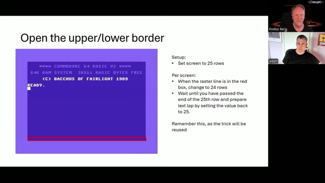
The C64 BASIC screen demonstrating the expansion of the lower border [ 00:43:05 ]
Flexible Line Distance (FLD) [45:55]
- Goal: Dynamically change the vertical spacing between character rows.
- Setup: No specific setup, but relies on raster timing.
- Per Raster Line:
- To prevent a "bad line" (which would reset the character row counter), change $D011 before the raster counter ($D012) matches its lower three bits to the lower three bits of $D011.
- By manipulating $D011, you can delay the appearance of a new character row, creating a gap.
- Ghost Byte: When a gap is created, the void is filled with the value from the last byte of the current VIC bank (e.g., $3FFF for the lowest bank). In ECM mode, this changes to $35FF. This "ghost byte" can be used for subtle graphical effects or to avoid conflicts with interrupt routines.

A C64 screen demonstrating Flexible Line Distance (FLD), showing how gaps between lines can reveal the "ghost byte" [ 00:45:58 ] - Example: The "Digesta" demo [1989] by Bacchus utilizes FLD to create dynamic text effects, showcasing the ghost byte for subtle visual elements.
![The 'Digesta' demo [<a href="https://youtube.com/watch?v=lLpXS6YiK3k&t=1989">1989</a>] by Bacchus, demonstrating Flexible Line Distance (FLD) and the 'ghost byte' effect](https://storage.googleapis.com/summarizer-images/images/lLpXS6YiK3k/sc0013_t00.48.46.webp)
The 'Digesta' demo [<a href="https://youtube.com/watch?v=lLpXS6YiK3k&t=1989">1989</a>] by Bacchus, demonstrating Flexible Line Distance (FLD) and the 'ghost byte' effect [ 00:48:46 ]
Line Crunch [49:49]
- Goal: "Crunch" each character row into a single pixel row, effectively scrolling the screen upwards.
- Setup: Set up a bad line on a given line.
- Per Raster Line:
- Trigger a bad line at the start of a line.
- Immediately (before cycle 14) negate the bad line condition (e.g., by changing $D011).
- The VIC chip will then increment its internal character row counter by a full character row (8 pixels) but only display the 7th pixel row of the intended character data.
- This effectively "eats up" 7 pixels per line, shifting the screen content upwards and displaying only one pixel line of each character row.
- This technique frees up CPU cycles because no more character data is read after the initial crunch, making it possible to combine with other effects.
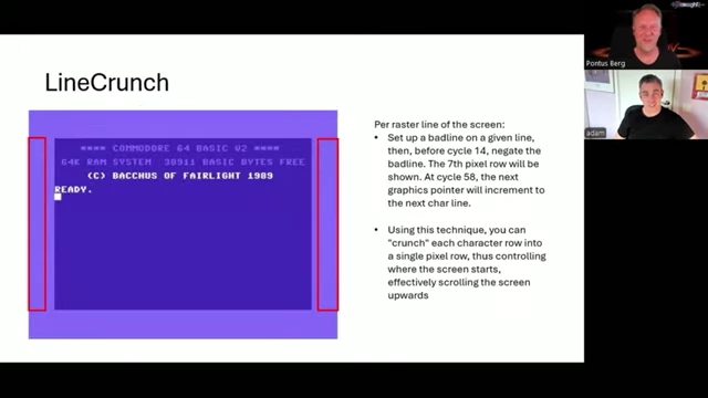
A C64 screen illustrating the "Line Crunch" effect, where character rows are compressed into single pixel lines [ 00:48:59 ] - Effect on BASIC Screen: Line crunch can reveal hidden memory areas on the BASIC screen due to the shifted counters.

Line crunch applied to the C64 BASIC screen, revealing normally hidden characters due to memory shifting [ 00:51:50 ] - Effect on Bitmap: When applied to bitmaps, line crunch produces a "noisy" top line, showing the 7th pixel row, which often needs to be hidden by sprites or border manipulation.

Line crunch applied to a bitmap picture, demonstrating the vertical compression and top-line noise artifact [ 00:55:38 ] - Advanced Application: The "Bonanza" demo by MDT [1988] uses line crunch to display seven sprites over a bitmap with open borders, a highly complex feat. This is possible because line crunch provides more CPU cycles by eliminating bad lines during the screen display.
![The 'Tetris' demo by MDT [<a href="https://youtube.com/watch?v=lLpXS6YiK3k&t=1988">1988</a>], displaying seven sprites in the border over a bitmap, utilizing line crunch for extra CPU cycles](https://storage.googleapis.com/summarizer-images/images/lLpXS6YiK3k/sc0018_t00.58.27.webp)
The 'Tetris' demo by MDT [<a href="https://youtube.com/watch?v=lLpXS6YiK3k&t=1988">1988</a>], displaying seven sprites in the border over a bitmap, utilizing line crunch for extra CPU cycles [ 00:58:27 ]
Virtual Screen Position (VSP) [01:03:39]
- Goal: Position the entire screen horizontally with minimal CPU time, allowing full-screen horizontal scrolling.
- Mechanism: Trigger a bad line right in the middle of the screen.
- Normally, bad lines are triggered by $D011 and $D012 matching.
- By putting the VIC chip in "idle mode" (preventing bad lines) and then setting the $D011 scroll bits to match $D012 at a specific horizontal cycle (e.g., cycle 16), a bad line is forced at that point.
- This misaligns the VIC's internal counters, causing the screen to be offset horizontally from that point onwards.
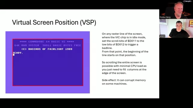
A C64 screen demonstrating Virtual Screen Position (VSP), allowing the entire screen content to be shifted horizontally [ 01:03:37 ]
- Side Effects: VSP can corrupt memory on some machines due to interactions between various C64 chips like the PLA. Strategies like avoiding specific memory locations or fixing the "glitch" are necessary.
- VSP Glitch: A visual artifact (often 3 characters of FF with a specific color) can appear in the top-left due to the CPU opcode following the $D011 store. This can be covered with a border or by creating another bad line immediately after the VSP trigger.
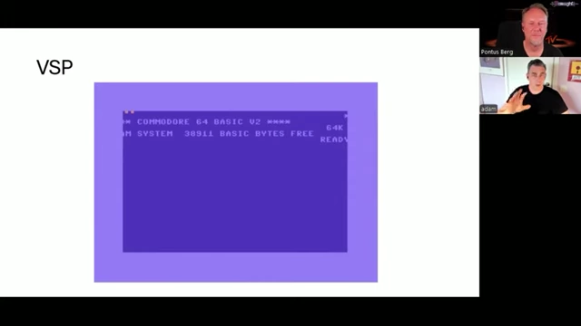
Virtual Screen Position (VSP) applied to the BASIC screen, highlighting the horizontal shift and the characteristic top-left glitch [ 01:07:49 ]
Any Given Screen Position (AGSP) [01:08:39]
- Goal: Combine line crunch (vertical scrolling) and VSP (horizontal scrolling) to position graphics at any arbitrary location on the screen.
- This technique, pioneered by MDT in their 1988 "Bonanza" demo, achieves complex full-screen movement by manipulating multiple VIC registers.
- When combined with line crunch, the noisy artifact lines from line crunch can be hidden by pushing the visible screen area down using FLD or covering them with sprites.
- AGSP enables dynamic, continuous scrolling effects, often achieved by feeding new graphic data as the screen moves, rather than shifting existing data.
The Bonanza demo by MDT, demonstrating Any Given Screen Position (AGSP) with complex full-screen graphics movement [ 01:10:01 ]
Flexible Line Interlace (FLI) [01:13:07]
- Goal: Circumvent the C64's color limitations to display more colors per 8x8 pixel cell, creating richer, higher-resolution graphics.
- Setup: Multicolor bitmap mode and multiple screen memories (at least 8).
- Mechanism:
- Per raster line, make $D018 (screen memory pointer) point to a new screen.
- At cycle 18 (or later), trigger a bad line. This forces the VIC to read color memory from the newly selected screen for that specific raster line.
- By rapidly switching the screen memory pointer and triggering bad lines, different sets of colors can be displayed on consecutive raster lines.
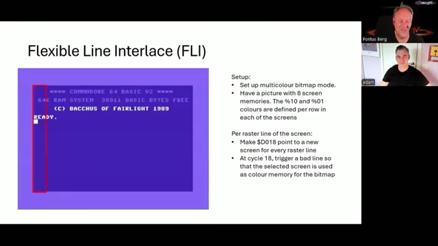
A C64 screen showcasing Flexible Line Interlace (FLI) with complex color patterns and the characteristic left-side artifact [ 01:13:06 ]
- FLI Bug/Glitch: Because the bad line must be triggered at cycle 18 or later, the first few character columns (typically 3) on the left side of the screen will display a corrupted area (often gray) due to the timing. This needs to be hidden or incorporated into the design.
- Example: The "Charlatan" demo by Beyond Force [1989] was the first to use FLI, demonstrating color splits and the left-side glitch.
![The 'Charlatan' demo by Beyond Force [<a href="https://youtube.com/watch?v=lLpXS6YiK3k&t=1989">1989</a>], featuring FLI color splits and an oscilloscope-like graphic](https://storage.googleapis.com/summarizer-images/images/lLpXS6YiK3k/sc0024_t01.16.13.webp)
The 'Charlatan' demo by Beyond Force [<a href="https://youtube.com/watch?v=lLpXS6YiK3k&t=1989">1989</a>], featuring FLI color splits and an oscilloscope-like graphic [ 01:16:13 ] - 4x4 Mode: A variation of FLI where the FLI technique is applied every fourth line, creating chunky 4x4 pixel areas with increased color depth.
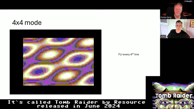
A C64 graphic demonstrating 4x4 mode, a variation of FLI that creates chunky pixel art with increased color depth [ 01:19:38 ]
Open All Borders (Escos) [01:19:58]
- Goal: Open all four screen borders (top, bottom, left, right) simultaneously, creating a truly full-screen display.
- Upper/Lower Border: Achieved by the 24/25 row trick (as in "Open Upper/Lower Border").
- Left/Right Border: Requires precise timing due to bad lines.
- Set the screen to 25 rows and 40 columns.
- At cycle 56 of the raster line, change to 38-column mode ($D016). This must be timed perfectly, usually using a Read-Modify-Write instruction (like INC or DEC $D016) which has specific cycle timings.
- Restore to 40 columns at any point during the next line.
- This technique is very challenging due to the cycle-accurate timing requirements.
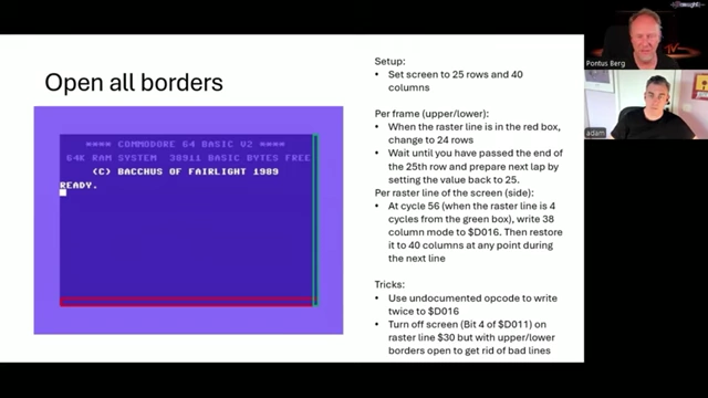
Setup for opening all four C64 screen borders, including parameters for upper/lower and left/right expansion [ 01:25:59 ] - Full Screen with No Bad Lines: By turning off the screen (bit 4 of $D011 set to zero) and then applying border opening techniques, one can achieve a full, blank screen without bad lines, making all CPU cycles available for other effects. This is complex as the borders must be continuously re-opened.
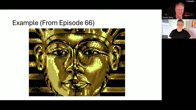
A C64 screen demonstrating the 'Escos' effect, showcasing sprites filling the entire screen beyond the traditional borders [ 01:26:55 ]
Dough Hook (Sprite Y-expansion trick) [01:32:02]
- Goal: Create a continuous, vertically repeating pattern from a single sprite by manipulating its Y-expansion.
- Mechanism:
- Set $D017 (sprite Y-expand) to 1 (expanded).
- Then, at a specific cycle (e.g., cycle 15), set it back to 0 (not expanded).
- By doing this repeatedly on every raster line, the same pixel row of the sprite can be made to appear again and again.
- This creates a stretched or repeated visual effect, allowing one sprite to fill large vertical areas.
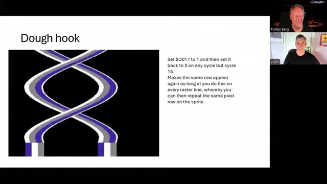
A C64 graphic demonstrating the "Dough Hook" sprite effect, showing a single sprite's top row repeated to create a continuous pattern [ 01:32:35 ]
Sprite Crunch [01:33:55]
- Goal: Manipulate the internal increment of sprite pointers, allowing sprites to appear sooner or later than their original 21 rows would dictate.
- Mechanism: Triggering $D017 from 0 to 1 and back to 0 at a very specific cycle (e.g., cycle 15) on a raster line.
- This "messes up" the VIC's internal logic for sprite counter increments, causing it to add a different value (e.g., 3 instead of 1), thus affecting the sprite's vertical length.
- This allows for complex, dynamic sprite re-positioning and resizing effects, and can even be combined with collision detection to dynamically determine sprite endings. This is considered one of the most technically brilliant and difficult C64 demo effects.
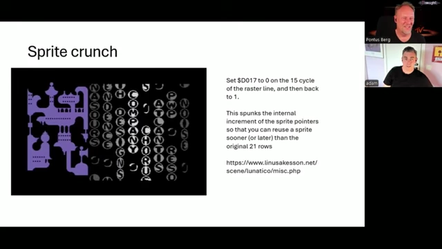
A complex C64 graphic illustrating "Sprite Crunch" and other sprite manipulations [ 01:33:55 ]