Rhino3D MatchSrf Command: A Comprehensive Guide to Surface Continuity and Matching Secrets
This video provides an in-depth explanation of the MatchSrf command in Rhino3D, crucial for achieving precise surface continuity.
- Continuity Options: Learn the differences between Position, Tangency, and Curvature, understanding how each affects control point movement.
- Advanced Features: Explore "Preserve Other End," "Average Surfaces" (useful for symmetrical models but requires caution), and "Match Edges by Closest Points" (essential for trimmed edges).
- Refine Match: Understand how it inserts control points to achieve target continuity, with a caveat about manually setting surface parameters.
- ISO Curve Direction: Discover how "Automatic" and "Preserve ISO curve direction" influence surface flow and how they are applied in different scenarios, especially with trimmed edges.
- Matching Secrets: Master the "Sculpt Low, Match High" workflow by increasing surface degree to achieve ultra-smooth, high-continuity matches, backed by numerical analysis.
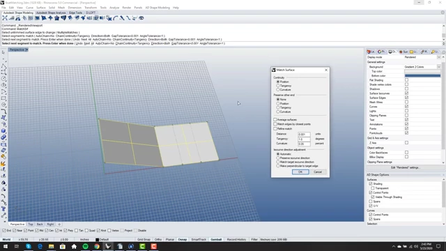
Rhino3D MatchSrf Command Options [ 00:01:40 ]
Understanding the MatchSrf Command [0:00]
The MatchSrf command in Rhino3D is essential for achieving precise surface continuity, particularly in the "sculpted match" workflow. This video aims to clarify the command's various options and when to use them effectively, saving users years of intuitive learning.
Core Continuity Options [1:38]
The video begins by demonstrating the fundamental continuity options using simple surfaces.
- Position (G0) [1:43]
- This option matches the edges by their position, ensuring they meet. It's the most basic level of continuity.
- Tangency (G1) [1:50]
- Selecting tangency moves the first row of control points (verts) inward from the edge. This aligns the direction of the surfaces at the edge.

Control points moved inward for Tangency (G1) continuity [ 00:02:00 ]
- Selecting tangency moves the first row of control points (verts) inward from the edge. This aligns the direction of the surfaces at the edge.
- Curvature (G2) [2:16]
- Curvature continuity moves two rows of control points inward from the edge, aligning both the direction and the rate of change of direction (curvature) of the surfaces.

Two rows of control points moved inward for Curvature (G2) continuity [ 00:02:20 ]
- Curvature continuity moves two rows of control points inward from the edge, aligning both the direction and the rate of change of direction (curvature) of the surfaces.
Preserve Other End [2:27]
This option determines whether the opposite end of the surface being modified retains its original condition.
- Choosing "None" allows the opposite end to be affected.
- "Tangency" and "Curvature" options maintain the original tangency or curvature of the opposite end, respectively.
- Using "Preserve Other End" with curvature on a low-degree surface automatically increases the surface's degree to accommodate the match, for example, from degree 3 to degree 5.

Surface degree increased to preserve curvature on the other end [ 00:03:36 ] - It's generally recommended to set the surface's degree appropriately from the beginning (e.g., degree 4 for tangency on one end and curvature on the other, or degree 5 for curvature on both ends) to avoid unexpected changes and reduce the need for this option.
Average Surfaces [5:47]
The "Average Surfaces" option modifies both surfaces being matched, rather than just one.
- Caution: This option tends to remain active after use, requiring users to manually uncheck it for subsequent operations to prevent unintended modifications to finalized surfaces.
- Useful Case: Symmetrical Models [7:14]
- It is highly useful for creating smooth transitions on symmetrical models (e.g., a car hood mirrored along a centerline).
- By mirroring one half and then using "Average Surfaces" with tangency matching, a perfectly smooth seam can be achieved across the centerline.

Seamlessly matched surfaces on a symmetrical model using Average Surfaces [ 00:08:30 ]
Match Edges by Closest Points [8:49]
This option tells the MatchSrf command to ignore the lateral distribution of control points along the edge when matching.
- Demonstrated Failure [10:04]
- When matching untrimmed edges with uneven control point distribution, using "Match Edges by Closest Points" can lead to visible gaps and distorted geometry, as it prevents the points from moving laterally to align perfectly.

Visible gaps and distorted verts resulting from "Match Edges by Closest Points" on uneven untrimmed edges [ 00:11:29 ]
- When matching untrimmed edges with uneven control point distribution, using "Match Edges by Closest Points" can lead to visible gaps and distorted geometry, as it prevents the points from moving laterally to align perfectly.
- Primary Use Case: Trimmed Edges [12:18]
- Trimmed edges are inherently "dirty" and often have complex, uneven control point distributions.
- Using "Match Edges by Closest Points" on trimmed edges helps preserve the existing, often desirable, point distribution while still achieving the desired continuity. It prevents lateral movement of control points, which would otherwise disrupt the trimmed edge's shape.
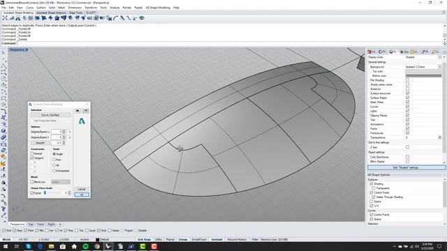
Trimmed edge surface with control points maintaining desired distribution [ 00:13:09 ]
- Problem with Split Edges [15:01]
- When working with split edges (which are essentially untrimmed but divided), "Match Edges by Closest Points" can prevent the endpoints from aligning, creating slivers or gaps.

Gap due to closest points on a split edge, preventing alignment of endpoints [ 00:17:25 ] - Unchecking "Match Edges by Closest Points" allows the endpoints to move and close the gap. Manually moving endpoints to align them before matching can also resolve such issues.

Gap closed on a split edge after unchecking "Match Edges by Closest Points" [ 00:18:39 ]
- When working with split edges (which are essentially untrimmed but divided), "Match Edges by Closest Points" can prevent the endpoints from aligning, creating slivers or gaps.
Refine Match [19:55]
"Refine Match" allows the command to insert new control points into the surface to achieve the desired continuity within the file tolerance.
- Impact on Geometry [21:26]
- This can significantly increase the control point count and degree of the surface, making it denser and potentially harder to control manually.

Surface showing a significant increase in control points after Refine Match [ 00:22:18 ]
- This can significantly increase the control point count and degree of the surface, making it denser and potentially harder to control manually.
- Recommendation: It's generally better to manually adjust the surface's degree and point count (parametrization) before matching, rather than relying on "Refine Match" to insert geometry, to maintain cleaner surface topology.
- Hidden Parameter Adjustment [25:40]
- "Refine Match" also offers a subtle capability to improve tangency beyond the default 1-degree target, forcing a tighter match without necessarily increasing geometry, if the surface structure already allows for it.
ISO Curve Direction Adjustment [27:43]
These options control how the internal structure (ISO curves and control points) of the surface behaves during matching.
- Automatic [28:35]
- The surface's ISO curves and control points will naturally follow the flow of the target surface, creating a smooth, organic transition. This is generally preferred for natural, flowing surfaces.

Surface flowing naturally with "Automatic" ISO curve direction adjustment [ 00:29:18 ]
- The surface's ISO curves and control points will naturally follow the flow of the target surface, creating a smooth, organic transition. This is generally preferred for natural, flowing surfaces.
- Match Target ISO Curve Direction [30:53]
- In practice, this option appears to function identically to "Automatic."
- Preserve ISO Curve Direction [31:38]
- This option maintains the original internal flow of the surface's control points and ISO curves while matching the angles of the edges. It is useful in two main scenarios:
- Non-standard patch layouts: When the desired flow is intentionally different from the target surface.
- Trimmed edges: To avoid inheriting the potentially "dirty" ISO curve direction of a trimmed edge, similar to using "Match Edges by Closest Points."
- This option maintains the original internal flow of the surface's control points and ISO curves while matching the angles of the edges. It is useful in two main scenarios:
- Make Perpendicular to Target Edge [34:49]
- This niche option forces the ISO curves of the matched surface to be perpendicular to the target edge. It's occasionally useful for specific blending scenarios where a sharp, perpendicular transition is desired.
Matching Secrets: Achieving Higher Continuity [36:45]
Achieving high-quality, "buttery smooth" matches often requires understanding limitations and employing strategic workflows.
- Numerical Evaluation of Continuity [37:09]
- Using tools like VSR Global Matching Analysis provides numerical feedback on G0 (positional), G1 (tangency break in degrees), and G2 (curvature discontinuity).
- G0 Tolerance: In real-world models, perfectly zero positional difference is ideal, but a small tolerance is acceptable.
- G1 Tolerance: While 1 degree is often considered tangent, a tighter tolerance (e.g., 0.2 degrees or less) is recommended for visually smooth surfaces.
- G2 Tolerance: Curvature continuity is the most challenging and often impossible to achieve perfectly in complex models. A practical tolerance (e.g., 0.5) is often sought.

VSR Global Matching Analysis interface showing G0, G1, and G2 numerical values [ 00:38:07 ]
- Limitations of Matching: Shared Verts [39:08]
- When two edges share a common vertex (especially in corners or complex patch layouts), that vertex must satisfy the continuity requirements of all adjacent edges. This shared constraint often limits how perfectly high-level continuity can be achieved.

Highlighted shared control points at a surface junction, illustrating matching limitations [ 00:41:17 ]
- When two edges share a common vertex (especially in corners or complex patch layouts), that vertex must satisfy the continuity requirements of all adjacent edges. This shared constraint often limits how perfectly high-level continuity can be achieved.
- The "Sculpt Low, Match High" Workflow [45:07]
- Sculpt Low: Design and sculpt primary surfaces using lower degrees (e.g., degree 5 or less). This allows for easier and more predictable direct control point manipulation.
- Match High: Once the overall shape and trims are established, progressively increase the surface's degree (e.g., to 6x6 or 7x7) and re-run the MatchSrf command with the desired continuity settings.
- Increasing the degree gives the surface more control points, allowing the MatchSrf command to find a tighter match without introducing visual kinks.
- Iteratively increasing the degree and applying the match command can significantly reduce G1 and G2 discontinuities to extremely low values.
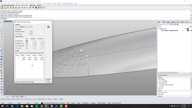
Improved numerical analysis results (G1, G2 values lower) after increasing surface degree [ 00:49:06 ]
- Benefits: This approach results in "ultra buttery smooth" surfaces where the seams are visually indistinguishable, even under intense reflection analysis.

Smooth, seamless surface after applying high-degree matching techniques [ 00:52:16 ]