Primary Surfacing: Advanced Patch Layout and the Trimmed Corner Technique for Solving 3-Sided Holes in NURBS Modeling
This video, part of the "Primary Surfacing" series, introduces the "trimmed corner" technique for NURBS modeling, specifically to address three-sided holes, a common challenge that can lead to surface singularities. The key steps include:
- Reworking initial geometry by moving the bow curve and ensuring curvature continuity.
- Generating the main aft hull surface using guide extrusions and the
surface from edge curvescommand. - Transforming the three-sided hole into a four-sided one by splitting the surface with an iso curve and creating a blend curve.
- Using
matchsurfandpullcommands to ensure surface continuity and watertightness. - Demonstrating how direct point editing on single-span surfaces can introduce complex design features like a concave bow or a transom reflex without redoing extensive curve networks.
- Emphasizing the efficiency and versatility of the trimmed corner technique, applicable to various design elements like wingtips, tablet edges, and aircraft canopies, promoting direct surface sculpting over convoluted curve-based workflows.
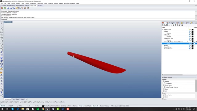
Final conceptual boat hull model with design features implemented [ 00:29:09 ]
Introduction to the Trimmed Corner [0:00]
This episode introduces the "trimmed corner," a fundamental technique in NURBS modeling for solving three-sided problems. This technique is frequently used to create complex shapes while maintaining surface quality and control.
The 3-Sided Hole Problem in NURBS Modeling [0:52]
The video begins by highlighting a common problem in NURBS modeling where a straight line segment at the bow of a boat hull creates a three-sided hole.
- Avoiding Singularities [1:06]: The goal is to fill this hole without collapsing surfaces into a singularity, which can lead to poor surface quality.
- Need for a Two-Patch Solution [1:41]: The presenter aims for a simple two-patch solution while maintaining control over the surface.
Reworking Geometry with Guide Extrusions [1:56]
To prepare for the trimmed corner technique, the initial geometry needs slight adjustments.
- Using Guide Extrusions [2:09]: The presenter advocates for using guide extrusions over guide curves, as detailed in a separate video, for their utility in such situations.
- Adjusting the Bow Curve [2:36]:
- The start of the bow curve is moved back.
- Curvature continuity is ensured using the
edge splittool to break the edge and thematchcommand (notmatch surf) to match the curve to the surface edge by curvature.
- Generating the Main Aft Surface [3:51]:
- The main hull surface for the aft part is generated using the
surface from edge curvescommand, leveraging clean, rebuilt edges from the guide extrusions. - The resulting surface inherits its degree (e.g., degree five in one direction, degree four in another) from the guide curves.
- The main hull surface for the aft part is generated using the
- Sculpting the Surface Directly [5:03]:
- The presenter demonstrates the ability to directly manipulate control points (verts) on the generated single-span surface to modify its shape (e.g., bulging it out, adjusting point spacing) while maintaining smoothness.
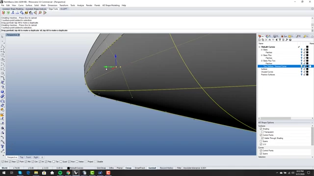
Direct manipulation of control points to sculpt the initial hull shape [ 00:05:19 ]
- The presenter demonstrates the ability to directly manipulate control points (verts) on the generated single-span surface to modify its shape (e.g., bulging it out, adjusting point spacing) while maintaining smoothness.
Converting to a 4-Sided Hole using the Trimmed Corner Technique [5:47]
The core of the trimmed corner technique involves transforming the problematic three-sided hole into a manageable four-sided hole.
- Splitting by ISO Curve [6:01]:
- The main surface is split by an iso curve, ensuring that the new edge acts like an untrimmed edge, which is crucial for maintaining surface quality and avoiding unnecessary trims.
- This creates a section of the surface that can be worked on independently.
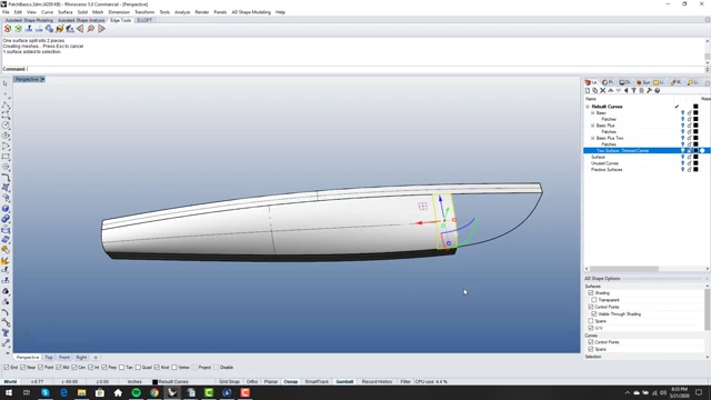
Splitting the main surface with an iso curve to create a new edge [ 00:06:19 ]
- Creating the Trim Curve [7:09]:
- A spherical trick is used: a sphere is placed at a corner point and intersected with the surface.
- An iso curve is extracted from this intersection point along the surface.
- A
blend curveis then created between this extracted iso curve and the main bow curve, resulting in a single-span, curvature-continuous curve. - This blend curve serves as the fourth edge, turning the three-sided problem into a four-sided one.
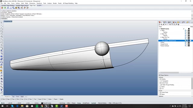
Using a sphere to create an intersection point, aiding in the creation of the trim curve [ 00:07:19 ]
- Filling the 4-Sided Hole [8:49]:
- The newly formed four-sided hole is filled using the
surface from edge curvescommand, selecting the four defining edges.
- The newly formed four-sided hole is filled using the
- Matching Surfaces for Continuity [9:52]:
- The new surface is matched to the adjacent main hull surface using the
matchsurfcommand. - Options like "tangency" or "curvature" are selected to ensure smooth transitions. The presenter notes a future video will deep-dive into
matchsurfoptions.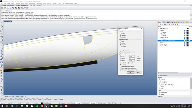
The 'Match Surf' dialog box for ensuring surface continuity (tangency or curvature) [ 00:10:08 ]
- The new surface is matched to the adjacent main hull surface using the
Finalizing the Trimmed Corner [11:27]
After creating and matching the new patch, the model is refined to a final, clean state.
- Trimming and Pulling the Edge [11:40]:
- The previous edge, which was matched to the guide curve, is now
pulledonto the surface of the main hull to create an accurate trim line.Pullis preferred overprojectfor better results. - The main surface is then split using this pulled curve, and the unwanted part is discarded.
- The previous edge, which was matched to the guide curve, is now
- Matching the New Trimmed Edge [12:19]:
- The edge of the newly trimmed surface is again matched using
matchsurfto the adjacent surface, typically for tangency and preserving iso curve direction.
- The edge of the newly trimmed surface is again matched using
- Combining Surfaces for a 2-Surface Model [13:09]:
- A key trick is demonstrated: because one part of the surface was split by an iso curve (not a true trim), it's still fundamentally part of the original larger surface.
- The surfaces are
untrimmed, their edges are duplicated, joined, and then the original large surface is split with these joined curves. This results in a final model composed of only two watertight surfaces, fulfilling the initial two-patch solution goal.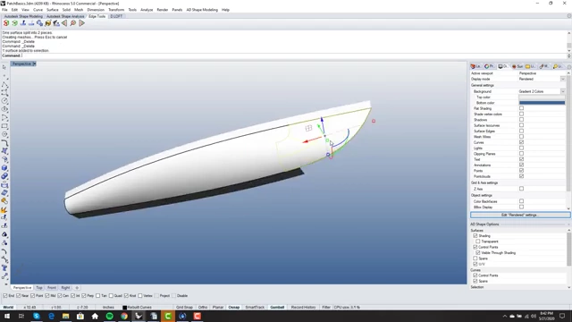
The final model composed of two watertight surfaces after the trimmed corner technique [ 00:13:48 ]
Analyzing Surface Quality [14:10]
The presenter uses specialized tools to assess the quality of the surfaces.
- VSR Shape Analysis [14:25]: The VSR Shape Analysis tool (a plugin for Rhino) is used to numerically check tangency and curvature continuity, providing more precise feedback than simple visual checks like zebra stripes.
- Achieving Watertightness and Smoothness [16:19]: The analysis confirms that the model is watertight and the surfaces exhibit high degrees of continuity, demonstrating the success of the single-span surface approach.
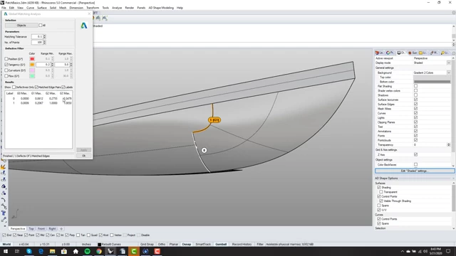
VSR Shape Analysis tool used to evaluate tangency and curvature continuity [ 00:15:00 ]
Incorporating Design Features with Point Editing [17:23]
A significant advantage of this workflow is the ability to easily modify the design by directly editing control points on the single-span surfaces.
- Adding a Concave Bow [18:25]:
- The model is reverted to an untrimmed state.
- Control points near the bow are manipulated to introduce a concave feature, replicating a design element seen in an example boat hull.
- The trimmed corner workflow (splitting by iso curve, creating blend curve, filling, matching, pulling, re-matching, and combining surfaces) is then reapplied to integrate this new feature smoothly.
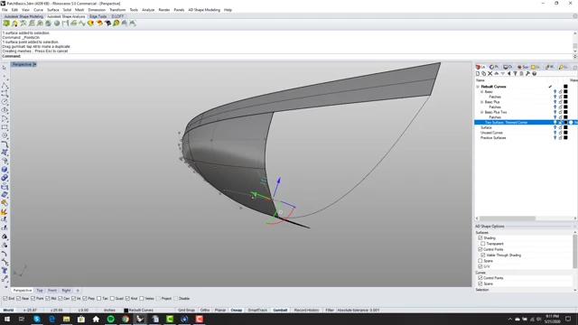
Directly manipulating control points to introduce a concave bow feature [ 00:18:37 ]
- Adjusting Transom Reflex [25:12]:
- The process is repeated to modify the transom (aft end) of the hull.
- By duplicating the edge, creating an orthographic curve, matching the edge to this curve, and then matching the surface, a smooth transition or "reflex" can be introduced at the stern, replacing a sharp edge.
- The changes propagate throughout the single-span surface, allowing for global design adjustments.
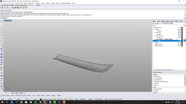
Adjusting control points to create a smooth reflex at the transom [ 00:26:05 ]
Adding a Bottom Blend [30:22]
To further refine the model, a blend is added to the bottom edge of the hull.
- Splitting and Blending [30:30]: The hull is split by iso curves along its bottom edges on both sides. These edges are then mirrored and a
blend surfcommand is used to create a smooth, softened transition along the keel. - Finished Conceptual Model [31:05]: The result is a nice, reasonable conceptual model of the boat with softened edges.
Conceptual boat hull model after adding a bottom blend and incorporating all design features [ 00:29:09 ]
The Power and Versatility of the Trimmed Corner [31:24]
The presenter emphasizes the widespread applicability of the trimmed corner technique.
- Broad Applications [31:38]: The trimmed corner is not just for boat hulls; it's used in designing:
- Wingtips (teardrop or scimitar style).
- Soft edges of tablets or iPads.
- Aircraft canopies.
- Aircraft noses, where collapsing to a singularity often leads to poor visual results.
- Solving Many Problems [32:51]: This technique solves numerous modeling challenges, providing clean, high-quality surfaces.
Workflow Efficiency [29:10]
The video concludes by advocating for a workflow that prioritizes direct surface sculpting over complex curve networks.
- Avoid "Rats Nests of Curves" [29:31]: The presenter advises against spending excessive time building intricate curve networks, as clients ultimately pay for the final surfaces, not the underlying curves.
- Direct Surface Manipulation [29:57]: Emphasizes that the quicker one can work directly on and sculpt surfaces, the more adaptable and efficient the design process becomes, allowing for rapid iteration based on client feedback without extensive rework of foundational curves.